Laminated composite lens

a composite lens and laminate technology, applied in the field of laminated composite lenses, can solve the problems of difficult lens removal due to adhesion, and achieve the effect of soft material

Active Publication Date: 2016-02-09
OCULAR SURFACE INNOVATIONS INC
View PDF34 Cites 1 Cited by
  • Summary
  • Abstract
  • Description
  • Claims
  • Application Information

AI Technical Summary

Benefits of technology

[0009]For segmented embodiments, the segmentation of the annulus serves as a relief for undesired expansion of the soft material on hydration, and prevents buckling or surface distortion due to expansion. The segmented annulus comprises a plurality of segments separated by spaces between segments, wherein the spaces provide for exchange of fluids from a post lens tear reservoir, which forms under the anterior rigid gas permeable layer. In addition, the spaces relieve lens-eye surface attraction, thereby facilitating lens removal. In some embodiment, (i) each segment comprises a sector of a peripheral portion of the lens ranging from 15 degrees to 30 degrees, (ii) a width of each space is 10 microns to 1000 microns, and (iii) a radial width of the soft annulus 2.5 mm to 5 mm. The thickness of the soft annulus may vary to accommodate ocular contour. In one embodiment, the segments are uniform in shape. In another embodiment, the segments are irregular and non-uniform, and the spaces between the segments are irregular and vary in width from the central zone to the most peripheral portion of the soft annulus.
[0010]Embodiments of the invention featuring a variation in the thickness of the soft annulus have the effect of reducing flexure in the rigid portion that would occur because of differences in the ocular contour. Another effect involves achieving rotational stability. Specifically, the conformance to ocular contour by the non-uniform thickness of the annulus produces rotational stability. The unequal thickness of the soft annulus can be orthogonal (90 degrees apart) or non-orthogonal (irregular) where the deepest and the shallowest regions are not 90 degrees apart.

Problems solved by technology

Such a lens requires tear exchange, freedom from scleral impingement, methods of managing flexure and air bubbles resulting from excessive clearance between the lens and the underlying eye, and a release of the surface attraction which causes difficulty in lens removal due to adherence.

Method used


Image

  • Laminated composite lens
  • Laminated composite lens
  • Laminated composite lens

Examples


Embodiment Construction

[0020]In the following paragraphs, the present invention will be described in detail by way of example with reference to the attached drawings. Throughout this description, the preferred embodiment and examples shown should be considered as exemplars, rather than as limitations on the present invention. As used herein, the “present invention” refers to any one of the embodiments of the invention described herein, and any equivalents. Furthermore, reference to various feature(s) of the “present invention” throughout this document does not mean that all claimed embodiments or methods must include the referenced feature(s).

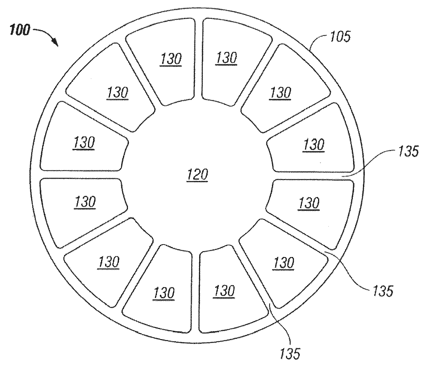
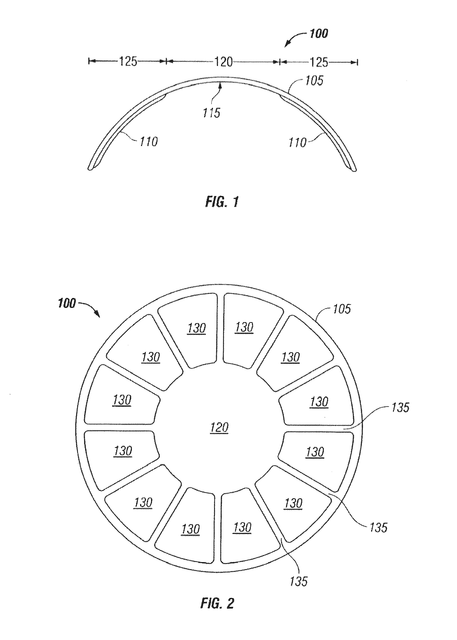
[0021]FIGS. 1 and 2 illustrate cross-sectional and side views, respectively, of a laminated composite lens 100 in accordance with the principles of the invention. Specifically, the composite lens 100 comprises an anterior rigid gas permeable layer 105 and an annulus 110 of soft material bonded to a posterior surface 115 of the anterior rigid gas permeable layer 105. ...


PUM


Abstract

A composite lens comprises an anterior rigid gas permeable layer, and an annulus of soft material bonded to a posterior surface of the anterior rigid gas permeable layer, wherein a central zone of the composite lens is rigid and without a soft layer, wherein a peripheral zone of the composite lens is generally rigid in its anterior aspect and soft in its posterior aspect.

Description

CROSS-REFERENCE TO RELATED APPLICATIONS[0001]This application is a continuation-in-part of U.S. patent application Ser. No. 13 / 801,754 filed Mar. 13, 2013, which is a continuation of U.S. Pat. No. 8,408,698 filed Mar. 18, 2010, the contents of which are incorporated herein by reference in their entireties.FIELD OF THE INVENTION[0002]The present invention relates generally to laminated composite lenses, and more particularly to laminated composite lenses having an annulus of soft material bonded to the posterior surface of an anterior rigid gas permeable layer.BACKGROUND OF THE INVENTION[0003]Refractive correction is achieved through use of spectacle lenses, contact lenses, corneal refractive surgery and intraocular lens implantation. Contact lenses have evolved from non-gas-permeable rigid lenses which made contact with the sclera and vaulted the cornea, to corneal contact lenses made of gas permeable products, and then to corneal-scleral contact lenses made of hydrogel materials. H...

Claims


Application Information

Patent Timeline
Patent Type & Authority Patents(United States)
IPC IPC(8): G02C7/04
CPCG02C7/049G02C7/04G02C2202/16
Inventor LEGERTON, JEROME, A.
Owner OCULAR SURFACE INNOVATIONS INC
Why Eureka
Try Eureka