Aircraft emergency landing route system

a technology for emergency landing and aircraft, applied in the field of aircraft, can solve the problems of not taking into account weather conditions, no-fly zones, and other obstacles, and requiring more attention

Active Publication Date: 2016-02-09
THE BOEING CO
View PDF29 Cites 91 Cited by
  • Summary
  • Abstract
  • Description
  • Claims
  • Application Information

AI Technical Summary

Problems solved by technology

However, during the flight of an aircraft, events may result in the use of a different landing site other than the destination airport.
Events such as thunderstorms, inconsistencies in the aircraft, changes in usable airspace, issues at the destination airport, and other events may result in an alternate landing site being selected for the aircraft.
These and other situations may be stressful and may require more attention from the pilot than desired.
These types of systems, however, do not take into account potential intervening terrain, no-fly zones, weather conditions, and other obstacles.

Method used


Image

  • Aircraft emergency landing route system
  • Aircraft emergency landing route system
  • Aircraft emergency landing route system

Examples


Embodiment Construction

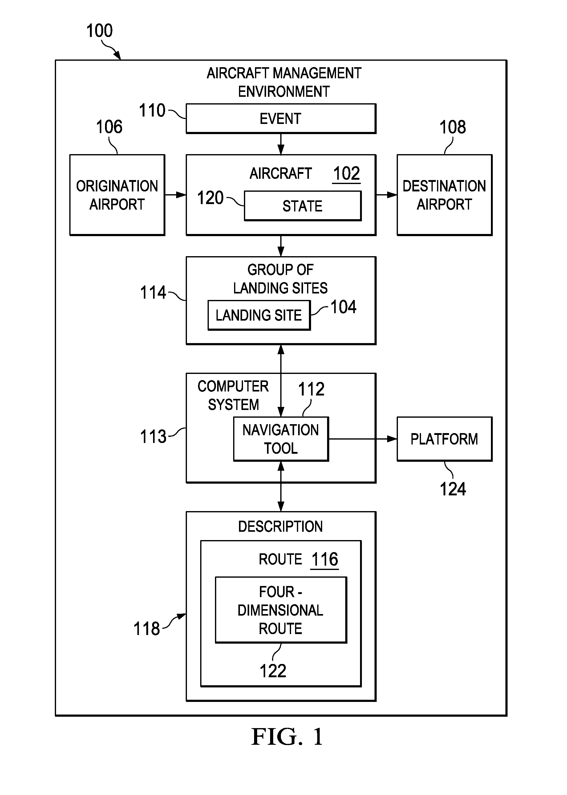
[0036]The illustrative embodiments recognize and take into account one or more different considerations. For example, the illustrative embodiments recognize and take into account that a route selection tool may be provided to the pilot to select a suitable landing site when an event requires the pilot to deviate from the planned destination airport.

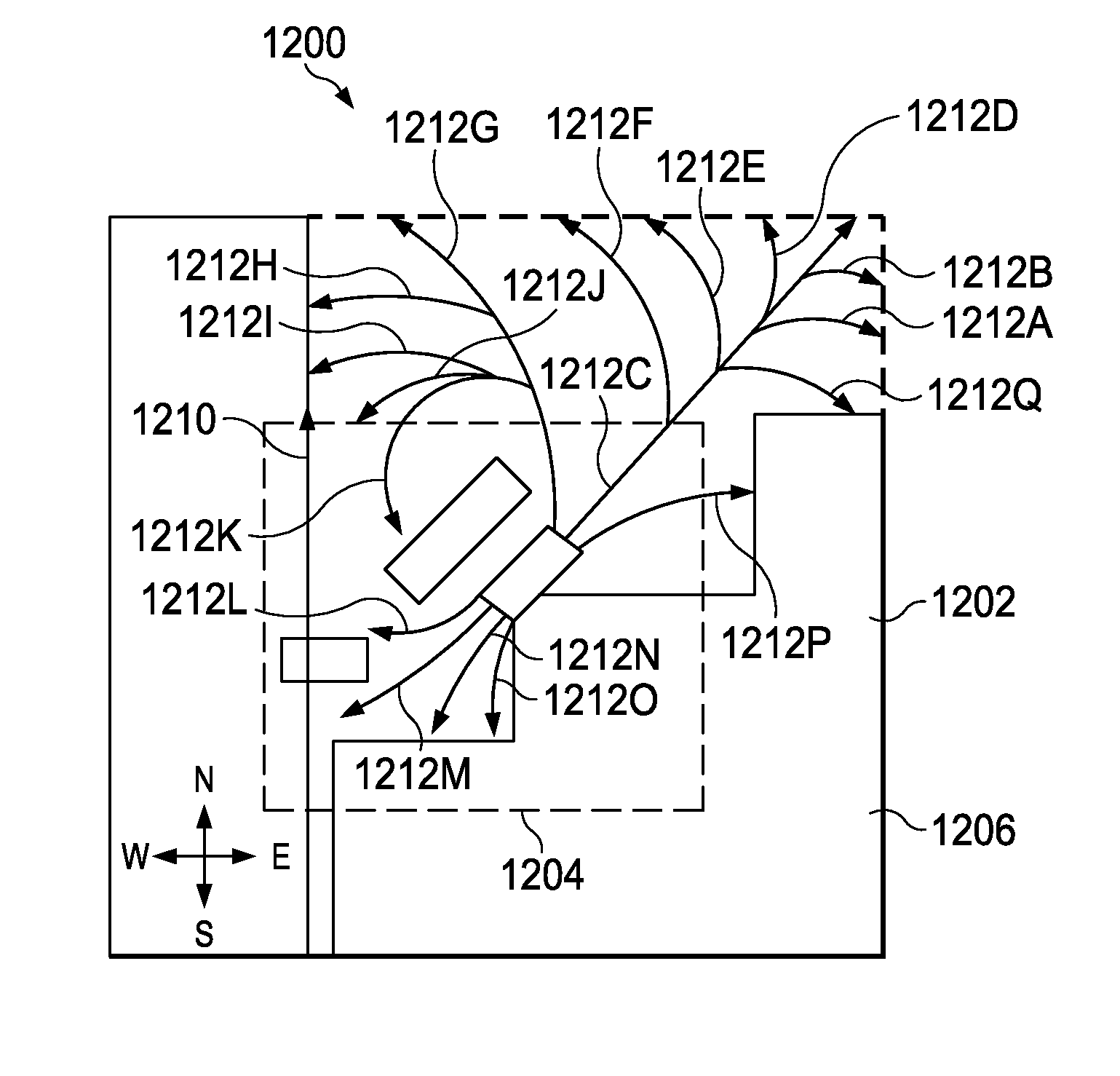
[0037]The illustrative embodiments also recognize and take into account that the selection of the landing site is only one part of the process that occurs in navigating the aircraft to that landing site. Further, the illustrative embodiments recognize and take into account that oftentimes, a straight point-to-point route from the current location of the aircraft to the landing site may be insufficient for desired flight of the aircraft. As a result, the route to the landing site is often more complex than a straight point-to-point route when obstacles that may be present between the aircraft and the landing site are taken into account.

[00...


PUM


Abstract

A method and apparatus for managing a landing site for an aircraft is presented. The landing site is selected from a group of landing sites. A description is communicated to a platform about a state of the aircraft along a route of the aircraft over time to the landing site. The aircraft is flown to the landing site using the description of the state of the aircraft along the route of the aircraft over time.

Description

CROSS-REFERENCE TO RELATED APPLICATION[0001]This application is a continuation-in-part of patent application U.S. Ser. No. 12 / 764,797, filed Apr. 21, 2010, Publication No. 2011 / 0264312, entitled “Determining Landing Sites for Aircraft,” which is incorporated herein by reference. This application is also related to the following patent application entitled “Predicting Aircraft Trajectory,” U.S. Ser. No. 12 / 679,275, filed Aug. 4, 2010, U.S. Publication No. 2010 / 0305781, assigned to the same assignee, and incorporated herein by reference.BACKGROUND INFORMATION[0002]1. Field[0003]The present disclosure relates generally to aircraft and, in particular, to landing sites for aircraft. Still more particularly, the present disclosure relates to a method and apparatus for describing a route to a landing site using a formal language.[0004]2. Background[0005]Commercial aircraft have planned routes from an originating airport to a destination airport. However, during the flight of an aircraft, e...

Claims


Application Information

Patent Timeline
Patent Type & Authority Patents(United States)
IPC IPC(8): G08G5/02G08G5/00
CPCG08G5/0039G08G5/02G08G5/0021G08G5/0056
Inventor OFFER, BRAD W.PARKS, PAUL CLARKBRUCE, ALAN EUGENESPINELLI, CHARLES B.REID, TRAVIS S.
Owner THE BOEING CO
Why Eureka
Try Eureka