Unmanned Aircraft and Operation Method for the Same

a technology of unmanned aircraft and operation method, which is applied in the direction of efficient propulsion technology, machines/engines, transportation and packaging, etc., can solve the problems of low power and low flight time, low storage density of contemporary batteries, and high cost of rotary piston engines, and achieves the effect of low power

Inactive Publication Date: 2015-10-08
AIRBUS DEFENCE & SPACE
View PDF13 Cites 114 Cited by
  • Summary
  • Abstract
  • Description
  • Claims
  • Application Information

AI Technical Summary

Benefits of technology

[0052]The internal combustion engine can operate without charging for higher altitudes and lower power. For slightly higher power, a first stage of charging is switched on. For even higher power, the second stage can then be triggered. Of particular interest is two-stage charging with further usage of the exhaust gas energy. Such two-stage charging is interesting for higher altitudes above around 4,000 m and can be used even at altitudes of about 10,000 m to 12,000 m.
[0053]Another interesting concept is the mechanica

Problems solved by technology

Currently, however, purely electric propulsion is only suitable for low power and low flight times. For example, a purely electric propulsion could be feasible for tactical UAVs with a maximum takeoff weight of up to about 70 kg in flight time

Method used


Image

  • Unmanned Aircraft and Operation Method for the Same
  • Unmanned Aircraft and Operation Method for the Same
  • Unmanned Aircraft and Operation Method for the Same

Examples


first embodiment

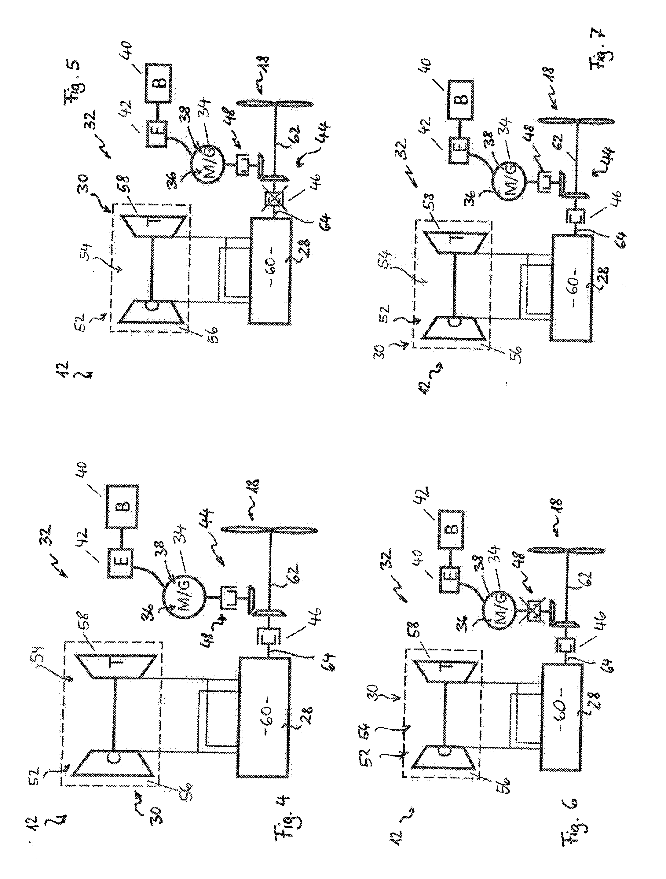
[0093]FIGS. 4 to 7 illustrate a first embodiment for the propulsion 12, with a single-stage charging, wherein only the first charger 52 is depicted, in the form of the exhaust gas turbocharger 54 with the compressor 56,C and the first exhaust gas turbine 58,T connected to the compressor 56. The internal combustion engine 28 and the electrical machine 34 can optionally be connected to the output shaft 62 and thus to the thrust generator18 via the first coupling 46 and the second coupling 48.

[0094]The propulsion 12 thus includes the internal combustion engine 28, which may be configured as a diesel engine and as a Wankel engine and is provided with a charging system in the form of the charger device 30 having the compressor 56 and the first exhaust gas turbine 58. The engine output shaft 64 can be connected to the thrust generator 18 via the first coupling 46. The generator 38 and the electric motor 36 or—as depicted here—the electrical machine 34 able to operate as a generator G or a...

third embodiment

[0109]FIGS. 12 to 17 illustrate the hybrid propulsion 32, as an example of the propulsion 12 for the UAVs 14, 24, 26, wherein identical or corresponding elements bear identical reference numerals as in the first two embodiments and reference can be made to the above statements for further details.

[0110]In this third embodiment, the charger device 30 is configured for switchable multi-stage charging and comprises the first charger 52 and a second charger 70 for providing the multi-stage charging, wherein the different chargers 52, 70 can be switched on or switched off under the control of the controller 50 in order to switch the different stages of charging on or off.

[0111]In the third embodiment of the hybrid propulsion 32, at least one electric motor 36,M and one generator 38,G are represented here in place of the electrical machine 34, which can operate in both the electric motor operation and the generator operation. The coupling device 44 comprises the first coupling 46 for coup...


PUM


Abstract

An unmanned aircraft includes a propulsion system having a diesel or kerosene internal combustion engine and a charger device for engine charging. The propulsion system can be a hybrid propulsion system or a parallel hybrid propulsion system.

Description

BACKGROUND AND SUMMARY OF THE INVENTION[0001]Exemplary embodiment of the invention relate to an unmanned aircraft, as well as to an operating method therefore.[0002]An unmanned aircraft, also known as a drone or an unmanned aerial vehicle (UAV), is a flying apparatus for unmanned aviation that can be used, for example, for surveillance, exploration, or reconnaissance, as a target drone, for measurement purposes, or even equipped with weapons, especially in combat zones. Drones can be used, for example, for military, secret services, or civilian purposes. A flying drone is unmanned, either automated via a computer program or controlled from the ground via radio signals or via satellite broadcasting. Depending on the application and equipment, drones can bear payloads, such as rockets for a military attack.[0003]In the commonly used terminology, such aircraft are customarily referred to by the abbreviation UAV, which stands for an “unmanned aerial vehicle”. Another abbreviation, UAS, ...

Claims


Application Information

Patent Timeline
IPC IPC(8): F02D29/02B64D27/02B64C39/02B64D31/00B64D41/00
CPCB64C2201/16F02D29/02B64D27/02B64D41/00B64C39/024B64D31/00B64D27/24B64D2027/026Y02T50/60Y02T50/40B64U50/11B64U50/34B64U70/60B64U70/80B64U50/19B64U10/25B64U50/33B64U10/17B64U30/297B64D35/08B64U10/10B64U30/10B64U30/20B64U50/00
Inventor STEINWANDEL, JUERGENSTAGLIANO, FLORIANVAN TOOR, JAN
Owner AIRBUS DEFENCE & SPACE
Why Eureka
Try Eureka