Unlock instant, AI-driven research and patent intelligence for your innovation.

Method for controlling a deceleration arrangement of a motor vehicle

a technology of deceleration arrangement and motor vehicle, which is applied in the direction of automatic initiation, braking system, transportation and packaging, etc., can solve the problems of adversely affecting the driving dynamics or controllability of the motor vehicle, and the distribution of braking torques on the individual axles can not be ideal, so as to prevent the possibility of a collision

Active Publication Date: 2016-02-16
ROBERT BOSCH GMBH
View PDF50 Cites 1 Cited by
  • Summary
  • Abstract
  • Description
  • Claims
  • Application Information

AI Technical Summary

Benefits of technology

[0012]In this way the control or regulation algorithms of a control device according to the invention that is implementing the method can be optimally adapted to the specified boundary conditions or the specific driving situation of the motor vehicle.
[0032]The surroundings detection device can basically be designed as desired. For example, the surroundings detection device can comprise a magnetic sensor, with which a generated magnetic field is changed by an object to be detected and said change is measured. Further, ultrasound-based surroundings detection devices are prior art. For example, an approach of the motor vehicle to an object, e.g. a different motor vehicle, can be detected by the surroundings detection device and an impending collision can be prevented.

Problems solved by technology

Depending on the braking situation an unbalanced and hence non-ideal distribution of the braking torques on the individual axles can occur.
An unbalanced brake force distribution in turn can adversely affect the driving dynamics or the controllability of the motor vehicle.

Method used


Image

  • Method for controlling a deceleration arrangement of a motor vehicle
  • Method for controlling a deceleration arrangement of a motor vehicle
  • Method for controlling a deceleration arrangement of a motor vehicle

Examples


Embodiment Construction

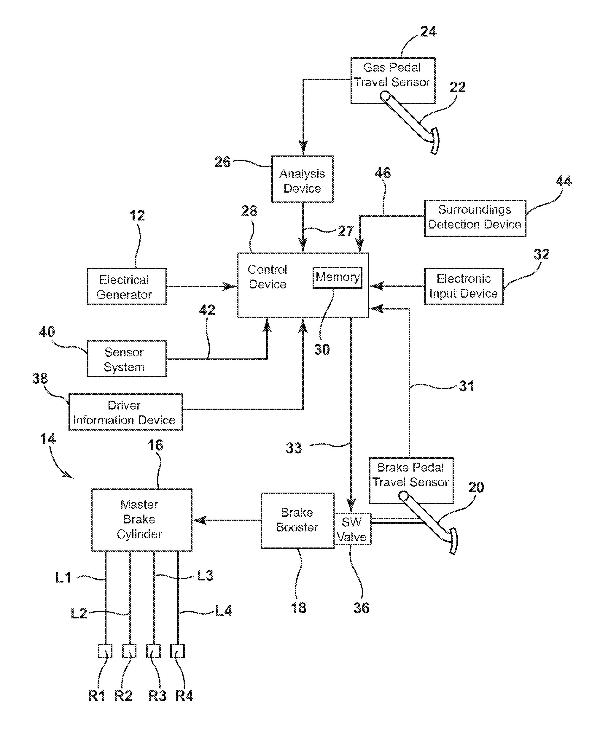
[0036]FIG. 1 shows a principle circuit diagram of a deceleration arrangement 10 for implementing the method according to the invention. The deceleration arrangement 10 is designed as a regenerative braking system, which also comprises, besides a frictional brake system 14, an electrical generator 12 and a control unit (inverter controller) for generating electrical energy. The generator 12 can e.g. be operated as a motor for driving the motor vehicle.

[0037]For example, only the two (not illustrated) front wheels or the front axle of the motor vehicle are / is connected to the generator 12. The total deceleration of the motor vehicle during a braking process is thereby composed of the deceleration components of the generator 12 and the frictional brake system 14.

[0038]The brake pressure required for the friction brakes R1, R2, R3, R4 is applied by means of a master brake cylinder 16 that is coupled to a brake pedal 20. For building up the brake pressure a brake medium is forced by the ...


PUM


Abstract

The invention relates to a method for controlling a deceleration arrangement (10) of a motor vehicle with at least one regenerative braking device (12) which is designed to decelerate the motor vehicle by means of a variable braking torque and to generate electrical energy corresponding to the braking torque. A return speed of an operating element for driving the motor vehicle, in particular an accelerator pedal (22), is detected (S2). A predefined braking torque is exerted (S5) by the regenerative braking device (12) if the return speed and / or a variable correlating thereto exceed(s) or fall(s) below a predefined threshold value.

Description

BACKGROUND OF THE INVENTION[0001]The invention relates to a method for controlling a deceleration arrangement of a motor vehicle, as well as a control device that is designed to carry out such a method.[0002]It is already known for hybrid vehicles or purely electrically driven vehicles to recover kinetic energy during braking processes by generator mode operation of the electrical machine and to charge a battery with said energy (regenerative braking) Here the electrical machine produces a negative drive torque, i.e. it operates as a generator. In the case in which the electrical machine is neither producing a positive nor a negative driving torque, the motor vehicle is not driven forwards and is only accelerated or decelerated because of external influences (e.g. air resistance, rolling resistance, road gradient) (said phenomenon is referred to in the English literature as “freewheeling”). In the case of negative driving torque the regenerative braking torque can be regulated as th...

Claims


Application Information

Patent Timeline
Patent Type & Authority Patents(United States)
IPC IPC(8): B60T7/12B60T1/10B60W10/188B60W10/08B60W50/10B60W30/18
CPCB60T7/12B60T1/10B60W10/08B60W10/188B60W30/18127B60W50/10B60T2220/02B60T2270/60B60W2540/10B60W2540/106B60W2550/20B60W2554/00
Inventor SCHULER, RALFKOBIELA, FANNYSTUETZLE, RUPERT
Owner ROBERT BOSCH GMBH