
Window lock

Active Publication Date: 2016-02-16
INTERLOCK USA
View PDF43 Cites 3 Cited by
  • Summary
  • Abstract
  • Description
  • Claims
  • Application Information

AI Technical Summary

Benefits of technology

The invention is a window lock that can adjust to different distances between the window frame and the pane. The lock includes a trigger that rotates to engage clips and hold the window in a locked position. The clips have surfaces that help bend the beam and raise the clip relative to the stops. The lock also includes a clip with a wider surface that engages with the stops at different positions, allowing for adjustable movement between the locked positions. The technical effects of the invention are improved usability and flexibility when adjusting the window lock.

Problems solved by technology

One disadvantage of this type of lock mechanism is that it normally requires the sashes be a certain distance away from one another.
When the sashes are too close to one another or too far apart the lock mechanism may be ineffective.
For example, if the sashes are spaced too far apart, the two parts of the lock mechanism may not be able to be joined together and the window sashes may not be locked.
If the sashes are too close to one another, the parts of the lock mechanism may bind or interfere with one another, resulting in the parts not being able to mate together and therefore the window sashes may not be locked.
When these problems occur during installation, the installer must adjust the window sashes and lock mechanism, numerous times, before achieving a proper fit between the sashes and lock mechanism.
These problems may also occur over time when windows become old, warped, or damaged through normal wear and tear.
As a result of the foregoing disadvantage, the lock mechanism and / or window sashes may need to be replaced without any assurance that the problems will not reoccur.
In addition, forcibly pushing the sashes together in order to bring them to a proper distance may result in stress upon the frame around the sashes and / or the glass panes.
Continuing to use the lock mechanism and window sashes in this fashion can exacerbate the problems.

Method used


Image

  • Window lock
  • Window lock
  • Window lock

Examples


Embodiment Construction

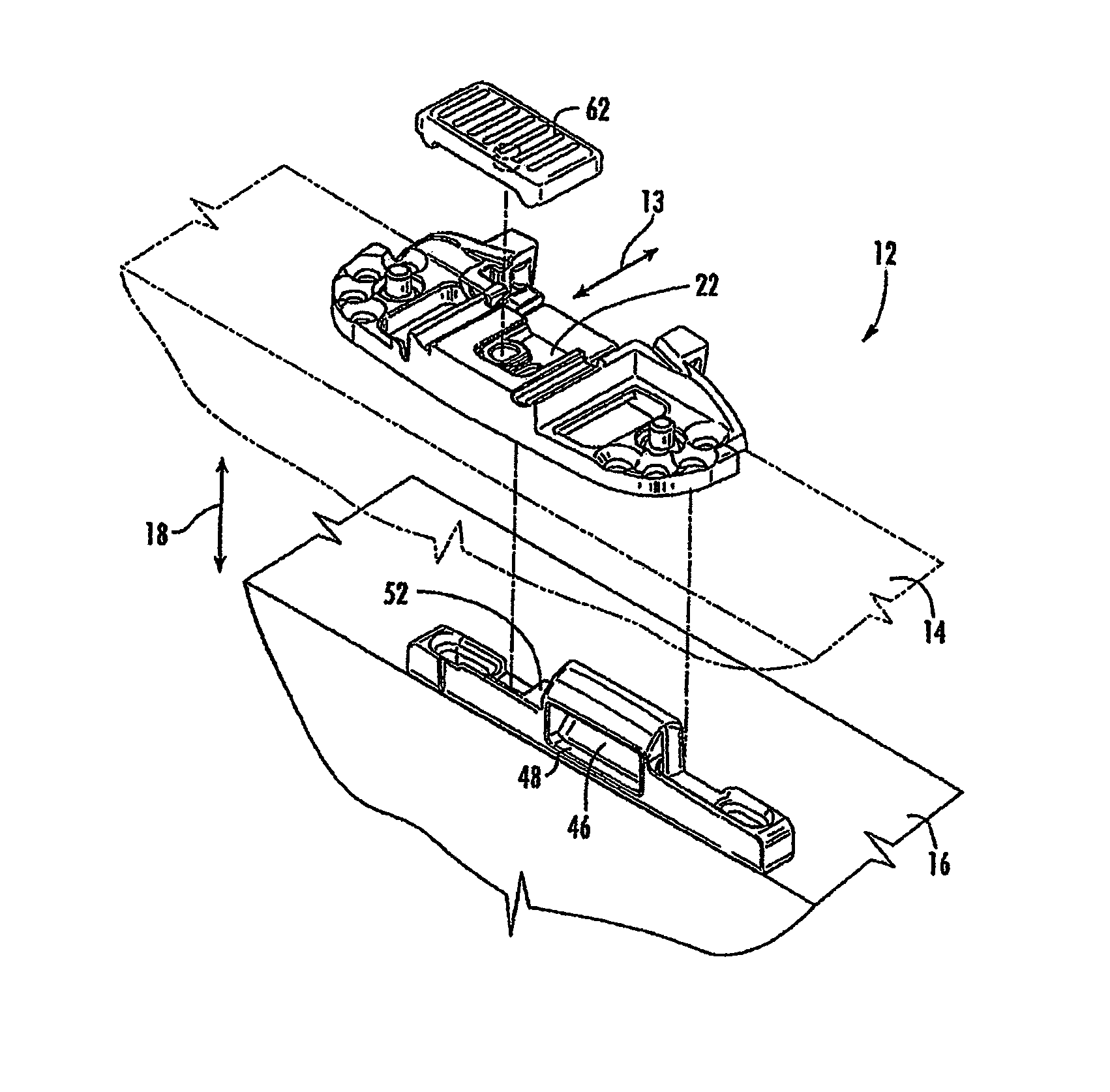
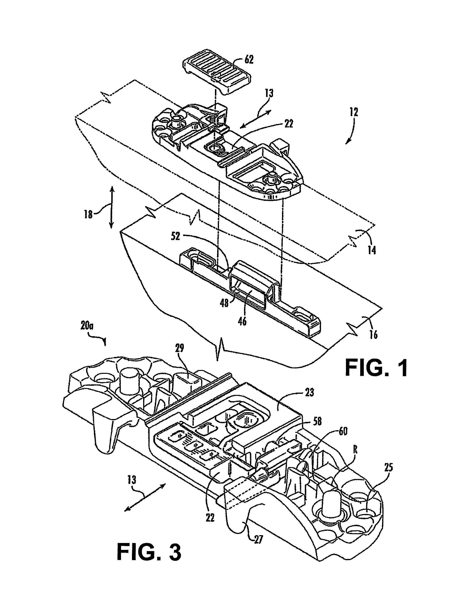
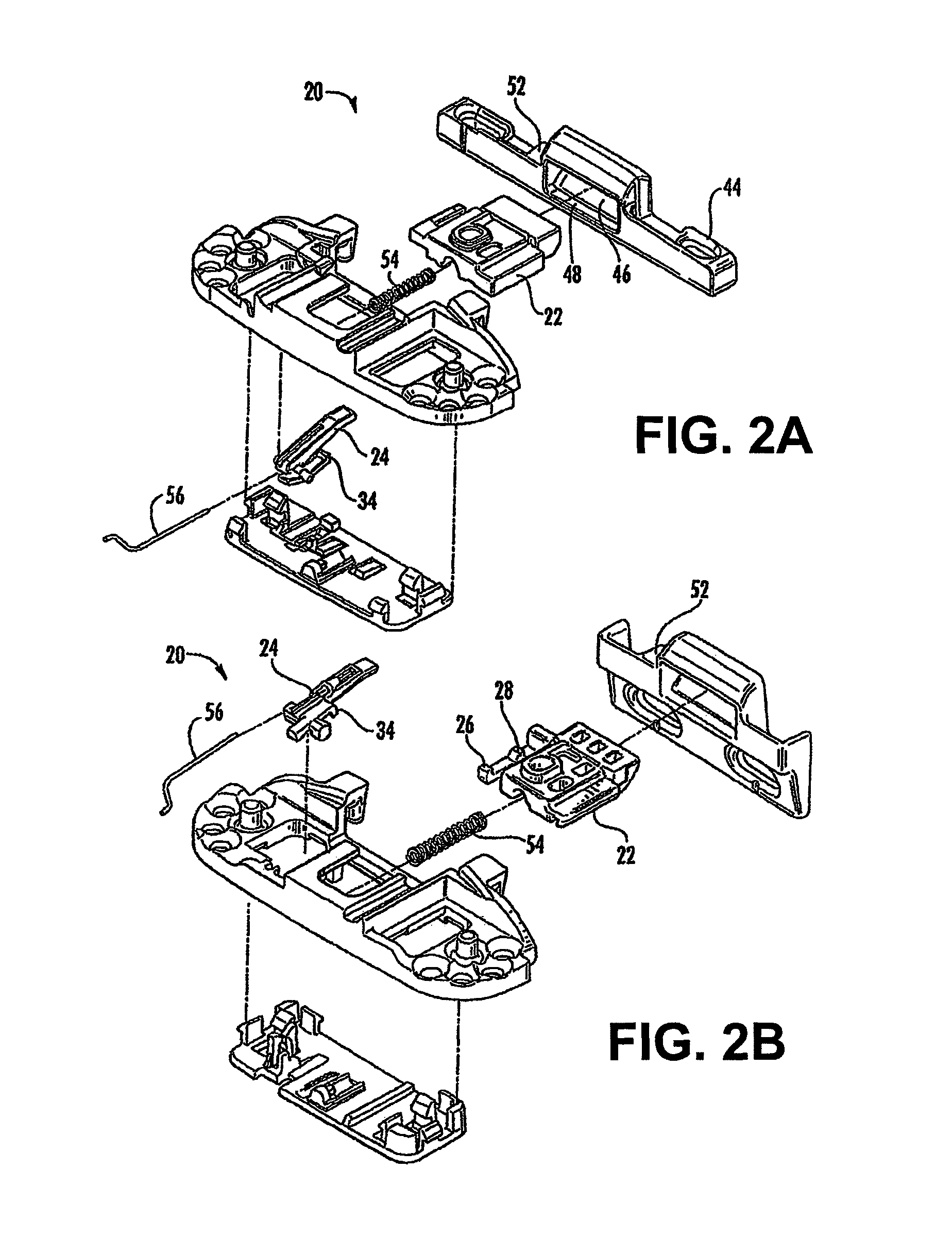
[0077]As shown in FIGS. 1, 2A, 2B, 4, and 5, window assembly 12 includes sashes 14, 16 that slide in parallel planes relative to one another in the direction of arrows 18, either vertically or horizontally. In the example used in the drawings, a vertically sliding window sash assembly is shown. (References to direction or movement up or down are with respect to the vertically sliding window sash example; for horizontally sliding window sashes these directions refer to right or left.) A lock 20 is attached to the adjacent sash portions 14 and 16 and includes a bolt 22 and a trigger 24 on a first lock portion 20a mounted on sash 14. Bolt 22 includes a first clip 26, a second clip 28, a beam 30, and pivot point 32 and where trigger 24 includes stop 34, axle 36, and ramp 38. Depending on the position of trigger 24 (explained below), bolt 22 moves in a direction normal to the planes of the sashes in direction of arrows 13, toward and away from sash 16. A second lock portion 20b is mounte...


PUM


Abstract

The invention relates to a window lock having a trigger and a bolt, the trigger being rotatable about an axis of rotation and the bolt being movable between a locked position, a first unlocked position and a second unlocked position. The bolt also includes a clip that engages first and second stops. The trigger rotates about the axis for engaging and disengaging the clip with the first and second stops. The first and second stops and the clip are all located on the same side of the axis of the trigger.

Description

CROSS REFERENCE TO RELATED APPLICATIONS[0001]This patent application is a continuation-in-part application of U.S. Patent Application Ser. No. 12 / 755,642, filed on Apr. 7, 2010, which claims priority to and the benefit of U.S. Provisional Patent Application No. 61 / 169,826 filed Apr. 16, 2009, titled “Window Lock,” which incorporated herein by reference in its entirety.FIELD OF THE INVENTION[0002]The invention relates to a lock mechanism for a window assembly.BACKGROUND OF THE INVENTION[0003]A double-hung, single hung, and double slider window assembly typically includes a window frame and a pair of window sashes mounted for vertical reciprocal sliding movement, one relative to the other, in guide rails of the master frame jamb of the window assembly.[0004]A traditional lock mechanism of the prior art, for a double hung window assembly usually includes one part of the lock on one sash and another part of the lock on the other sash, wherein joining the two parts of the lock mechanism ...

Claims


Application Information

Patent Timeline
IPC IPC(8): E05C3/16E05C1/10E05C7/00E05C1/08E05C1/04
CPCE05C1/10E05C1/08E05C1/04E05C2007/007E05B63/20E05B65/0864Y10T292/0969Y10T292/1023Y10T70/5146Y10T292/096
Inventor RUSPIL, MATHEW, D.
Owner INTERLOCK USA
Learn More