Decompression device and method

Pending Publication Date: 2022-03-31
BILEK THOMAS A
View PDF0 Cites 1 Cited by
  • Summary
  • Abstract
  • Description
  • Claims
  • Application Information

AI Technical Summary

Benefits of technology

[0007]In some embodiments, a method for back stretching using a decompression device may include the steps of: positioning the harness loop to extend around a back portion of an upright torso of a user; placing a contact surface of the base on a support object so that the cross brace is positioned above a head and the upright torso of the user; and leaning the user's head and front shoulders/clavicle over the base while maintaining the longitudinal axis to be substantially parallel with the user's torso.
[0008]In further embodiments, the device may comprise a positional motivator which may be configured to govern the distance that the traction surface may be positioned from the support structure. The device may include a support structure having a first cross brace. A harness having a traction surface may be movably coupled to the first cross brace. A positional motivator may couple the harness to the support structure, optionally via an extension. The positional motivator may be configured to control the distance between the traction surface and the first cross brace.
[0009]In still further embodiments, the device may include a positional motivator which may be configured to govern the distance that the base may be positioned from the support structure. The device may inclu

Problems solved by technology

However, these devices are typically costly, not portable, and/or not suitable for home use or travel.
Unfortunately, users may not be readily able to attach the devices to such structures due to their back pain.
Other users may inco

Method used


Image

  • Decompression device and method
  • Decompression device and method
  • Decompression device and method

Examples


Embodiment Construction

[0037]The terminology used herein is for the purpose of describing particular embodiments only and is not intended to be limiting of the invention. As used herein, the term “and / or” includes any and all combinations of one or more of the associated listed items. As used herein, the singular forms “a,”“an,” and “the” are intended to include the plural forms as well as the singular forms, unless the context clearly indicates otherwise. It will be further understood that the terms “comprises” and / or “comprising,” when used in this specification, specify the presence of stated features, steps, operations, elements, and / or components, but do not preclude the presence or addition of one or more other features, steps, operations, elements, components, and / or groups thereof.

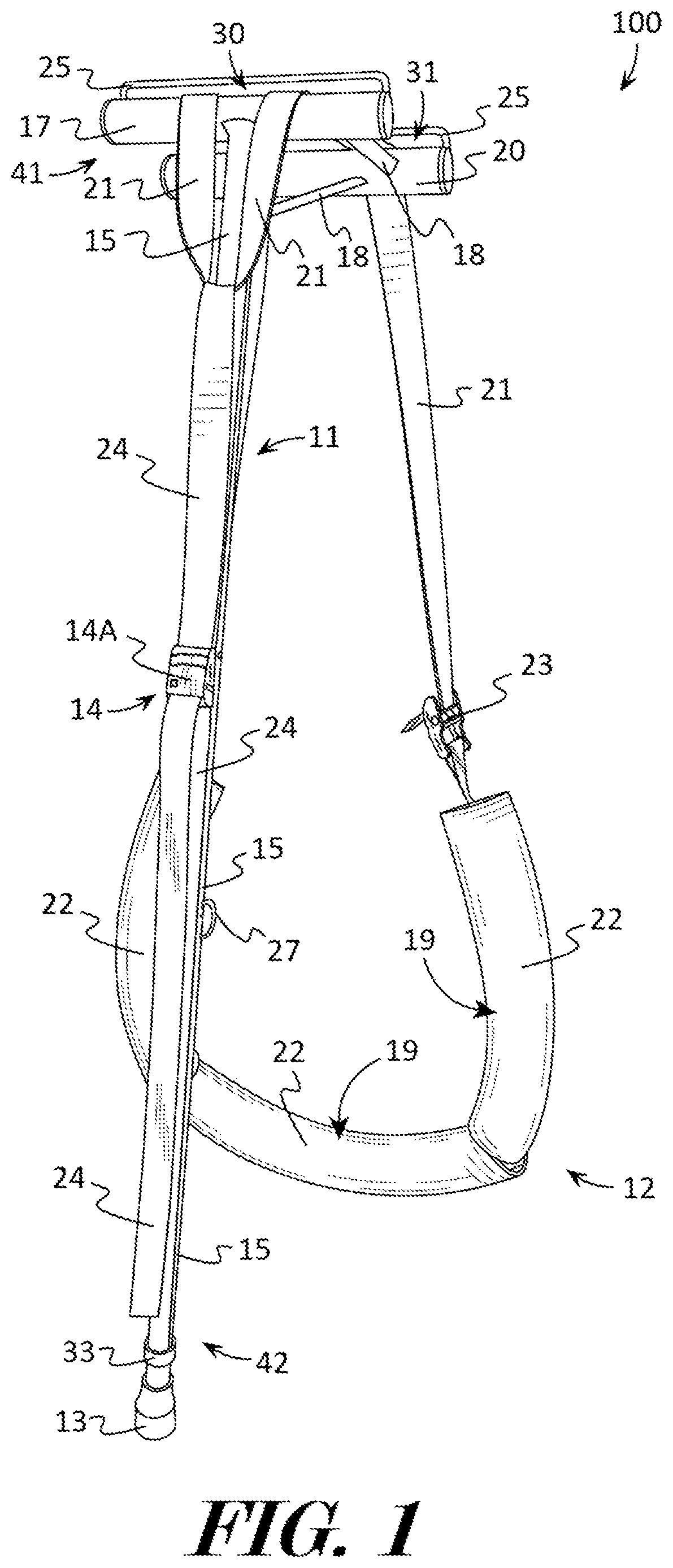
[0038]For purposes of description herein, the terms “upper”, “lower”, “left”, “center”, “right”, “rear”, “front”, “side”, “vertical”, “horizontal”, and derivatives thereof shall relate to the invention as oriented in FIG...


PUM


Abstract

A decompression device and a method using the decompression device are provided. The device includes a support structure having a longitudinal brace, and a cross brace that may be coupled to or part of the longitudinal brace. A harness may be coupled to the cross brace, and the harness may have a traction surface. An adjustable fastener may control the harness length therein controlling the distance between the traction surface and the first cross brace. The base positioned on a surface or structure, and portions of the harness positioned around the body of a user, such as under the arms and around the back. The user may manipulate the adjustable fastener to position portions of the harness a desired distance from the cross brace. The user may then leans forwards tilting the decompression device and the harness will provide lift, and therefore decompression, to the back of the body of a user.

Description

CROSS REFERENCE TO RELATED APPLICATIONS[0001]This application is a CIP of Ser. No. 16 / 664,328, filed on Oct. 25, 2019, which claims benefit of Ser. No. 62 / 769,062, filed on Nov. 19, 2018, and which is a CIP of Ser. No. 15 / 970,320, filed on May 3, 2018 which claims benefit of Ser. No. 62 / 503,618, filed on May 9, 2017 and claims benefit of Ser. No. 62 / 522,965, filed on Jun. 21, 2017, all of which are incorporated by reference in their entirety.FIELD OF THE INVENTION[0002]This patent specification relates to the field of therapeutic orthopedic devices. More specifically, this patent specification relates to devices and methods configured to provide decompression to a body.BACKGROUND[0003]Many individuals suffer from chronic back pain. While surgery, drug therapy, and chiropractic manipulation are employed for the treatment of back pain, the use of traction or decompression therapy and back stretching is preferable to many individuals. Decompression therapy may help relieve many types o...

Claims


Application Information

Patent Timeline
IPC IPC(8): A61H1/02
CPCA61H1/0229A61H2201/1652A61H2201/1253A61H2201/1621A61H2201/1676A61H2205/081A61H1/0292A61H2201/0134A61H2201/0149A61H2201/0157A61H2201/0192A61H2201/1269A61H2201/1418A61H2201/1626A61H2201/1633A61H2201/169A61H2201/5053A61H2203/0487A61H2203/0425A61H2203/0406A61H2201/1654
Inventor BILEK, THOMAS A.
Owner BILEK THOMAS A
Why Eureka
Try Eureka