Method and system for removing material from a workpiece

a technology of workpieces and materials, applied in metal-working equipment, belt grinding machines, manufacturing tools, etc., can solve problems such as adding to the difficulty of the finishing process

Active Publication Date: 2017-03-30
SAINT GOBAIN ABRASIVES INC +1
View PDF19 Cites 0 Cited by
  • Summary
  • Abstract
  • Description
  • Claims
  • Application Information

AI Technical Summary

Benefits of technology

[0009]According to another embodiment, a system for conducting a material removal operation includes a platen having a receiving surface including at least one opening configured for the flow of an ejection material therethrough; and a coated abrasive configured to be translated over the receiving surface of the platen; and movement assembly configured to move the platen relative to a workpiece and control a distance between the coated abrasive and the workpiece for a material removal operation.

Problems solved by technology

Generally, each of the blades is in form of an airfoil having a complex curvature, thus adding to the difficulty in the finishing process.

Method used


Image

  • Method and system for removing material from a workpiece
  • Method and system for removing material from a workpiece
  • Method and system for removing material from a workpiece

Examples


embodiments

[0103]Embodiment 1. A method of removing material from a workpiece comprising: moving a coated abrasive over a receiving surface of a platen, the receiving surface comprising at least one opening configured for the flow of an ejection material therethrough; moving the platen and workpiece relative to each other to contact the coated abrasive to the workpiece and removing material from the workpiece; and controlling a flow pressure for the ejection material through the at least one opening during removing material from the workpiece, wherein the flow pressure of the ejection material is adjusted based on at least one of the operation parameters from the group: a translation rate of the coated abrasive over the receiving surface; the weight of the coated abrasive; a material removal rate; a coefficient of friction between the coated abrasive and the platen; a tension on the coated abrasive; or a combination thereof.

[0104]Embodiment 2. A method of removing material from a workpiece com...

example

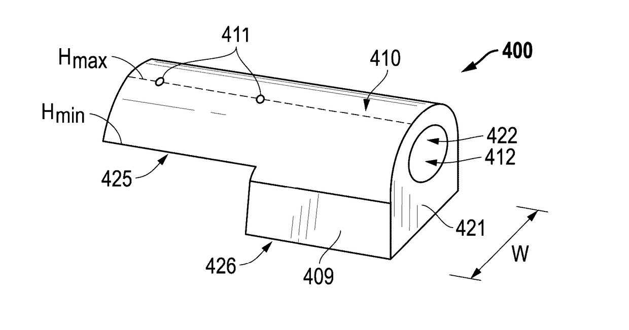
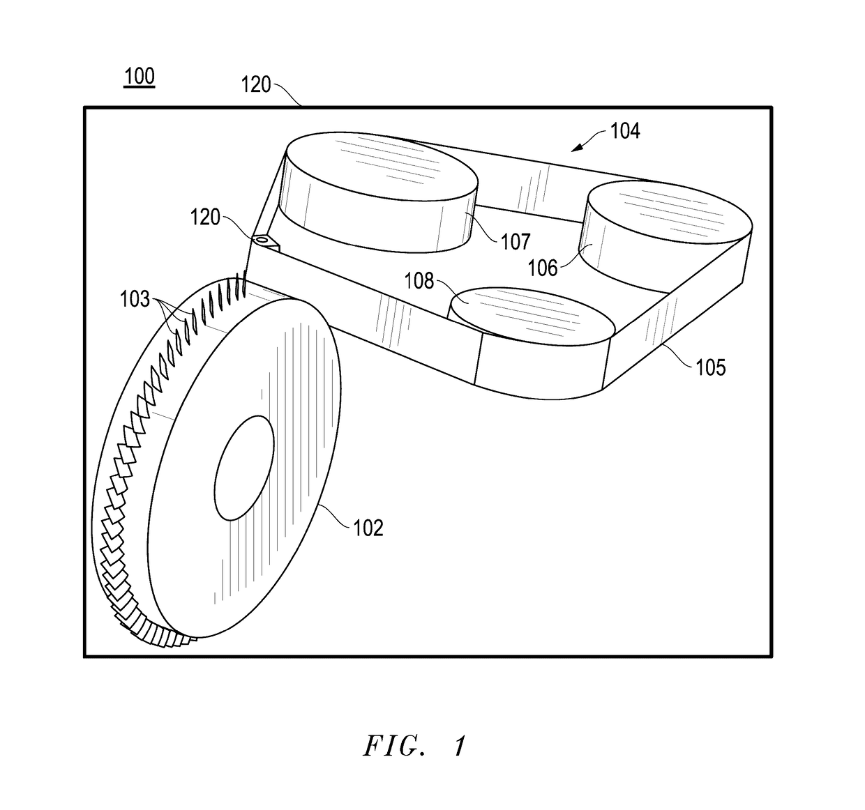
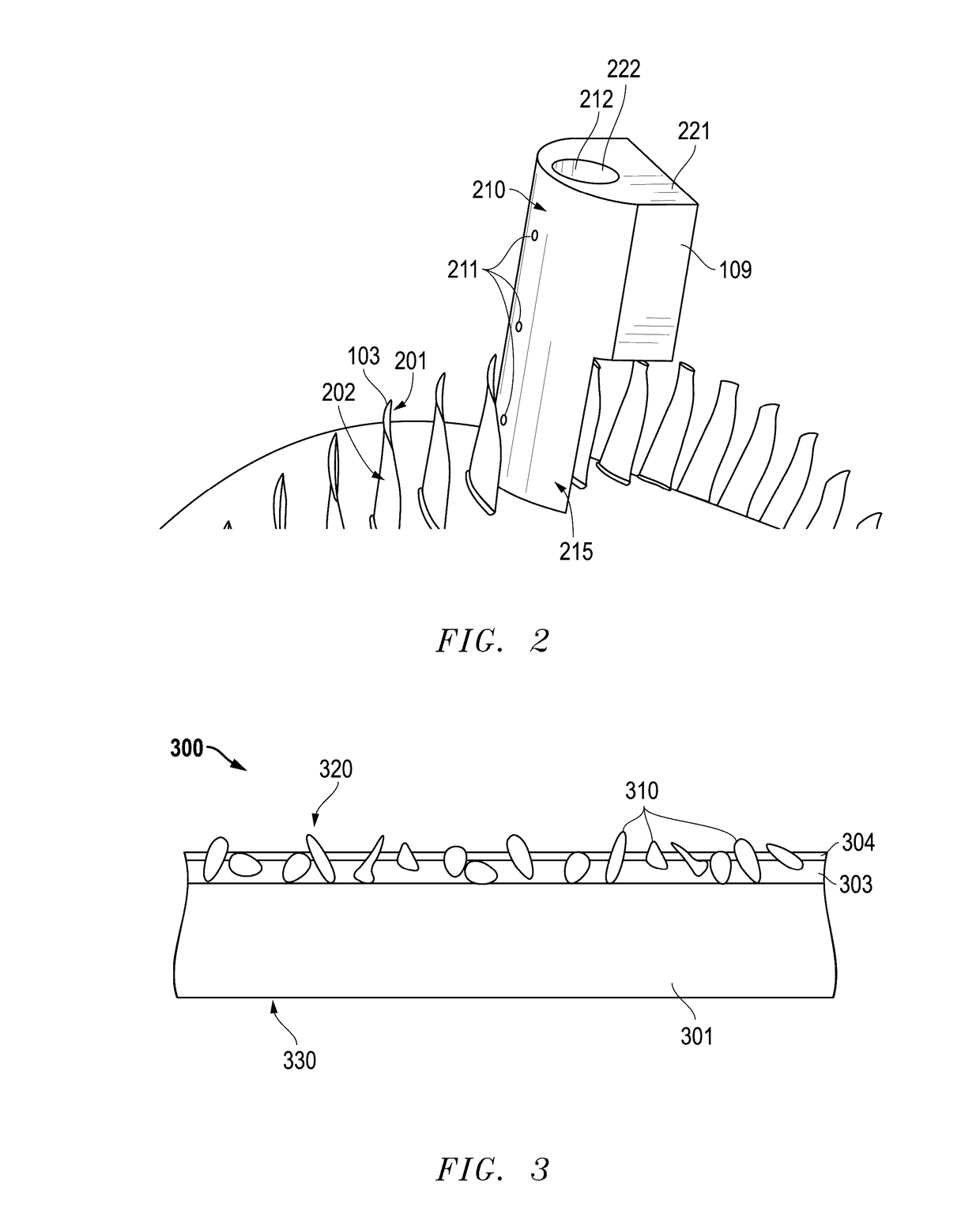
[0163]A first coated abrasive belt (S1) commercially available as Norax X30-U243 from Saint-Gobain Abrasives Corporation was attached to a belt sanding machine commercially available as Model #67912 from Dynabrade Corporation. The machine was altered to include an adapter configure to incorporate a platen having three openings within a receiving surface, each of the openings having a diameter of approximately 1.6 mm, and longitudinally spaced apart from each other along the longitudinal axis of the receiving surface by a distance of 1.5 cm. The receiving surface had a radius of curvature of approximately 1.5 cm.

[0164]A first test (T1) was conducted using the first coated abrasive belt S1, wherein the belt was run on the machine and over the receiving surface platen at a translation rate of 25 m / s. The temperature of the abrasive surface of the coated abrasive belt belt was measured at three different positions using an infrared thermometer device commercially available from Commerci...


PUM

PropertyMeasurementUnit
thicknessaaaaaaaaaa
thicknessaaaaaaaaaa
flow pressureaaaaaaaaaa

Abstract

A method of removing material from a workpiece includes moving a coated abrasive over a receiving surface of a platen, the receiving surface having at least one opening configured for the flow of an ejection material therethrough, moving the platen and workpiece relative to each other to contact the coated abrasive to the workpiece and removing material from the workpiece, and controlling a flow pressure for the ejection material through the at least one opening during removing material from the workpiece, where the flow pressure of the ejection material can be adjusted based on at least one of the operation parameters such as a translation rate of the coated abrasive over the receiving surface, the weight of the coated abrasive, a material removal rate, a coefficient of friction between the coated abrasive and the platen, or a combination thereof.

Description

CROSS-REFERENCE TO RELATED APPLICATION(S)[0001]This application claims priority under 35 U.S.C. §119(e) to U.S. Patent Application No. 62 / 234,021 entitled “METHOD AND SYSTEM FOR REMOVING MATERIAL FROM A WORKPIECE,” by John S. Hagan et al., filed Sep. 28, 2015, which is assigned to the current assignee hereof and incorporated herein by reference in its entirety.FIELD OF THE DISCLOSURE[0002]The following is directed to a method of removing material from a workpiece, and more particularly, a method of using a coated abrasive and platen to remove material from a workpiece.DESCRIPTION OF THE RELATED ART[0003]Gas turbine engines typically include a plurality of sections mounted in series. Two of the sections are the turbine section and the compressor section. These sections each include a plurality of rotors, each mounting a plurality of circumferentially spaced blades.[0004]One recent development in gas turbine engines is the integrally-bladed rotor (IBR). Such components include a hub, ...

Claims


Application Information

Patent Timeline
Patent Type & Authority Applications(United States)
IPC IPC(8): B24B19/14
CPCB24B19/14B24B21/08B24B21/16B24B55/02B24D11/00
Inventor HAGAN, JOHN S.MCNAMEE, ROBERT J.LANDES, TONYRUTKIEWICZ, BRIANLANG, WILLIAMSHAPPELL, MIKE D.
Owner SAINT GOBAIN ABRASIVES INC
Why Eureka
Try Eureka