
Power distribution system, and switchgear assembly, and mounting member therefor

a technology of power distribution system and switchgear, which is applied in the direction of substation/switching arrangement details, substation/switching arrangement board/panel/desk, electrical apparatus, etc., can solve the problems of large electrical switching apparatus such as, for example, some medium-voltage and low-voltage circuit breakers, and achieve the effect of reducing the size of the electrical switching apparatus

Inactive Publication Date: 2016-02-16
EATON CORP
View PDF4 Cites 2 Cited by
  • Summary
  • Abstract
  • Description
  • Claims
  • Application Information

AI Technical Summary

Benefits of technology

[0009]These needs and others are met by embodiments of the disclosed concept wherein a mounting member is provided which among other benefits, allows a metering module to be accommodated by an electrical switching apparatus when the electrical switching apparatus is installed inside of a mounting element.

Problems solved by technology

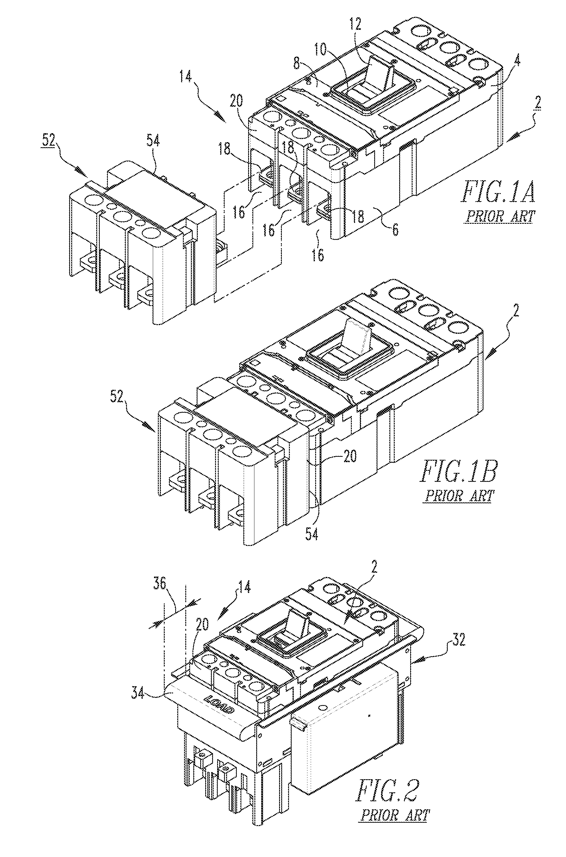
Additionally, some electrical switching apparatus such as, for example, some medium-voltage and low-voltage circuit breakers, can be relatively large.

Method used


Image

  • Power distribution system, and switchgear assembly, and mounting member therefor
  • Power distribution system, and switchgear assembly, and mounting member therefor
  • Power distribution system, and switchgear assembly, and mounting member therefor

Examples


Embodiment Construction

[0027]As employed herein, the term “number” shall mean one or an integer greater than one (i.e., a plurality).

[0028]As employed herein, the statement that two or more parts are “connected” or “coupled” together shall mean that the parts are joined together either directly or joined through one or more intermediate parts.

[0029]As employed herein, the statement that two or more parts or components “engage” one another shall mean that the parts touch and / or exert a force against one another either directly or through one or more intermediate parts or components.

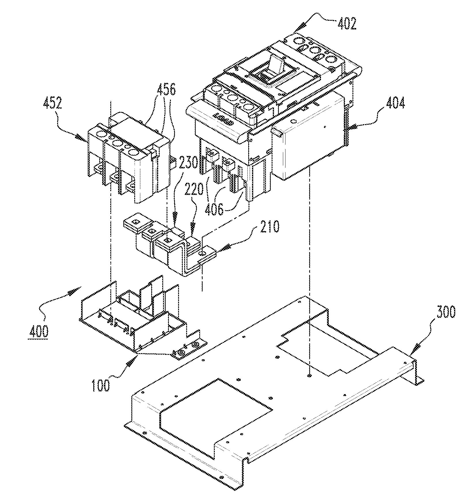
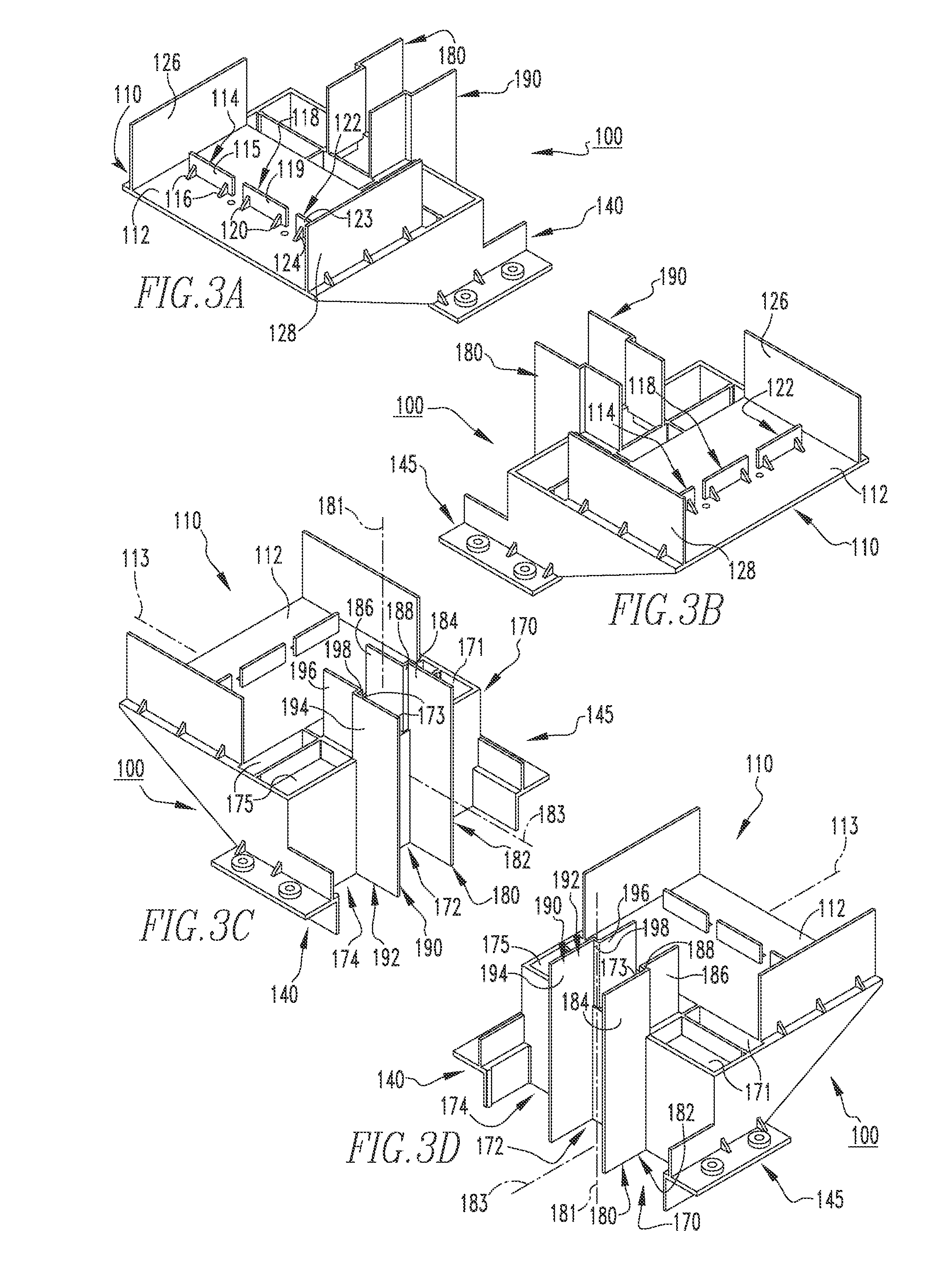
[0030]FIGS. 3A, 3B, 3C and 3D show a mounting member 100 that may be used in a switchgear assembly (e.g., without limitation, switchgear assembly 400 shown in FIGS. 6A, 6B, 7A and 7B). As seen, the mounting member 100 includes a base portion 110 structured to retain a metering module (e.g., without limitation, power monitoring metering module 452 shown in FIGS. 6A, 6B and 7A). Continuing to refer to FIGS. 3A, 3B, 3C and 3D, the ...


PUM


Abstract

A mounting member for a switchgear assembly is provided. The switchgear assembly includes a mounting element, an electrical switching apparatus having a number of terminals and being coupled to the mounting element, a metering module having a number of terminals and being spaced from the electrical switching apparatus, a number of electrical conductors electrically connecting the terminals of the metering module to the terminals of the electrical switching apparatus, and a support member adjacent the electrical switching apparatus. The mounting member includes a base portion structured to retain the metering module; a number of coupling portions structured to couple the mounting member to the support member; and a number of directing portions, each directing portion being structured to receive a corresponding one of the electrical conductors.

Description

BACKGROUND[0001]1. Field[0002]The disclosed concept pertains generally to power distribution systems and, more particularly to power distribution systems including electrical enclosures such as for example, panelboards and switchboards. The disclosed concept also pertains to switchgear assemblies for power distribution systems, such as for example, electrical switching apparatus including a metering module. The disclosed concept further relates to mounting members for switchgear assemblies.[0003]2. Background Information[0004]Electrical switching apparatus used in power distribution systems are often mounted within a switchgear enclosure either individually or in combination with other switchgear (e.g., without limitation, circuit switching devices and circuit interrupters such as circuit breakers, contactors, motor starters, motor controllers and other load controllers). Molded case circuit breakers, for example, include at least one pair of separable contacts which are operated ei...

Claims


Application Information

Patent Timeline
Patent Type & Authority Patents(United States)
IPC IPC(8): H02B1/04H02B1/03
CPCH02B1/04H02B1/03H02B1/042
Inventor CROOKS, WILLIAM MICHAELFLORENCE, DAWN S.
Owner EATON CORP
Learn More