Method for identifying damage on transmissions

a transmission and damage technology, applied in the direction of instruments, structural/machine measurement, vibration measurement in solids, etc., can solve the problems of peaks or edges in the signal caused by damage, and achieve the effect of keeping operating restrictions and stopping the machin

Inactive Publication Date: 2016-02-23
SIEMENS AG
View PDF18 Cites 3 Cited by
  • Summary
  • Abstract
  • Description
  • Claims
  • Application Information

AI Technical Summary

Benefits of technology

[0015]The inventive consideration of the torque acting on the transmission during signal analysis allows purely operational changes in the oscillation signals to be separated from changes due to damage. To this end, the detected oscillation signals may be normalized for example to the inventively determined torque through application of different known mathematical or function-dependent methods. This ensures reliable damage identification and prediction in a simple manner and thus also economical operation of the system comprising the transmission.
[0027]According to another advantageous feature of the present invention, the temperature of the transmission and / or of the apparatus comprising the transmission may be monitored and also included in the evaluation of the oscillation signal in respect of possible damage. The condition of the transmission oil, in particular the viscosity and / or purity and / or moisture content and / or further characteristic values of the transmission oil may advantageously also be monitored and included in the evaluation of the oscillation signal in respect of possible damage. The detection of further operational parameters and their consideration in the analysis of the oscillation signals allow operational changes to be separated from changes due to damage. When a large number of operating parameters are detected, it is possible in particular to establish multi-parameter links by way of known mathematical methods, thereby allowing reliable damage identification and prediction.

Problems solved by technology

Damage can be identified when monitoring the condition of the transmission with vibration transducers, because deformations of the transmission components caused by wear and damage also produce a change in detected oscillation signals.
Peaks or edges in the signal caused by damage may also be displaced.

Method used


Image

  • Method for identifying damage on transmissions
  • Method for identifying damage on transmissions
  • Method for identifying damage on transmissions

Examples


Embodiment Construction

[0033]Throughout all the figures, same or corresponding elements may generally be indicated by same reference numerals. These depicted embodiments are to be understood as illustrative of the invention and not as limiting in any way. It should also be understood that the figures are not necessarily to scale and that the embodiments are sometimes illustrated by graphic symbols, phantom lines, diagrammatic representations and fragmentary views. In certain instances, details which are not necessary for an understanding of the present invention or which render other details difficult to perceive may have been omitted.

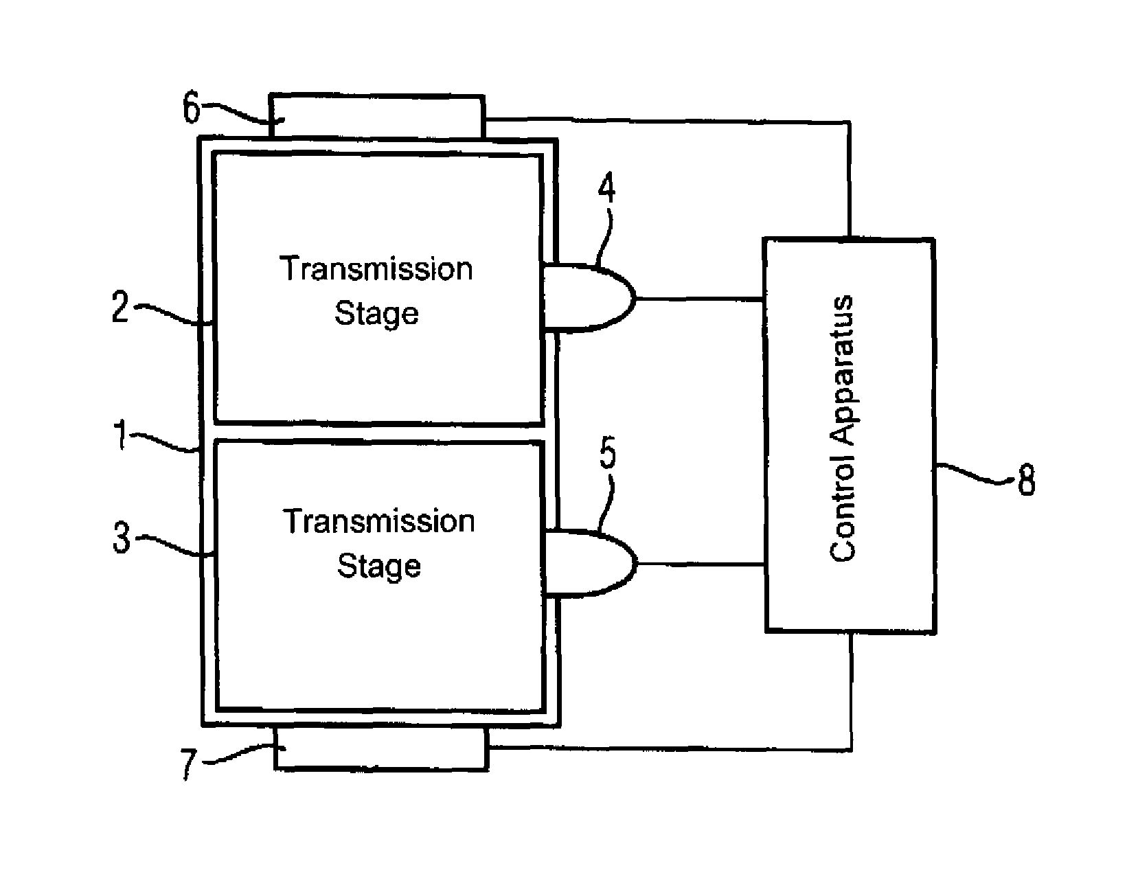
[0034]Turning now to the drawing, and in particular to FIG. 1, there is shown a schematic diagram of a transmission 1, as used for example in wind power plants to convert the rotational movement of the rotor to a rotation of the drive shaft of a generator. The transmission 1 comprises two toothed transmission stages 2, 3, to each of which a vibration transducer 4, 5 and a ro...


PUM


Abstract

A method for identifying possible damage in a toothed transmission stage having at least one pair of engagement toothed wheels includes measuring with a vibration transducer an oscillation signal corresponding to oscillations produced by a rolling and impact motion when teeth of a pair of the toothed wheels mesh under load during operation of the transmission stage, comparing the oscillation signal with a calibration oscillation signal, determining a torque acting on the transmission stage from a difference between the oscillation signal and the calibration oscillation signal, and evaluating the measured oscillation signal commensurate with the determined torque to identify the possible damage to the transmission stage.

Description

CROSS-REFERENCES TO RELATED APPLICATIONS[0001]This application claims the priority of European Patent Application, Serial No. 11174330.8, filed Jul. 18, 2011, pursuant to 35 U.S.C. 119(a)-(d), the content of which is incorporated herein by reference in its entirety as if fully set forth herein.BACKGROUND OF THE INVENTION[0002]The present invention relates to a method for identifying damage in toothed transmission stages having at least one pair of meshing toothed wheels and to an apparatus for identifying damage on toothed transmission stages.[0003]The following discussion of related art is provided to assist the reader in understanding the advantages of the invention, and is not to be construed as an admission that this related art is prior art to this invention.[0004]Transmissions are central components in a large number of industrial machines. During operation they are subject to a high level of stress and associated wear, leading to the possibility of damage occurring, which mig...

Claims


Application Information

Patent Timeline
Patent Type & Authority Patents(United States)
IPC IPC(8): G01M13/02
CPCG01M13/028
Inventor KLEIN-HITPASS, ARNOREIMERS, JAN-DIRK
Owner SIEMENS AG
Why Eureka
Try Eureka