LED lens and LCD backlight screen

a technology of led lenses and backlight screens, which is applied in the field of new led lenses and lcd backlight screens, can solve the problems of not meeting the needs of users to lcd, high cost of lcd backlight sources, etc., and achieves the effect of reducing projection distance and large ratio of distance to heigh

Active Publication Date: 2016-03-08
DONGGUAN OUKE OPTOELECTRONICS TECH
View PDF2 Cites 4 Cited by
  • Summary
  • Abstract
  • Description
  • Claims
  • Application Information

AI Technical Summary

Benefits of technology

[0022]The present invent takes the above-mentioned structure, and provides a totally new refractive optical LED lens, to achieve the intention of acquiring the same brightness and evenness degree through reducing the projection distance by half (to achieve the large ratio of distance to height) compared to the present refractive optical lens with the same arrangement distance, utilizing the optical basic theory combined with computer simulation technology.
[0023]After the present invention has made the exit surface a bending surface with a certain extent, the scope of the light emitted from LED after passing the lens is bigger, and when it is used on the LCD backlight screen, the backlight effect of the LCD backlight screen is more well-distributed.

Problems solved by technology

Obviously, the longer the projection distance, the higher the cost of LCD backlight source, and it doesn't meet the need of the users to the LCD illuminating apparatus as lightness and thinness.

Method used


Image

  • LED lens and LCD backlight screen
  • LED lens and LCD backlight screen
  • LED lens and LCD backlight screen

Examples


example 1

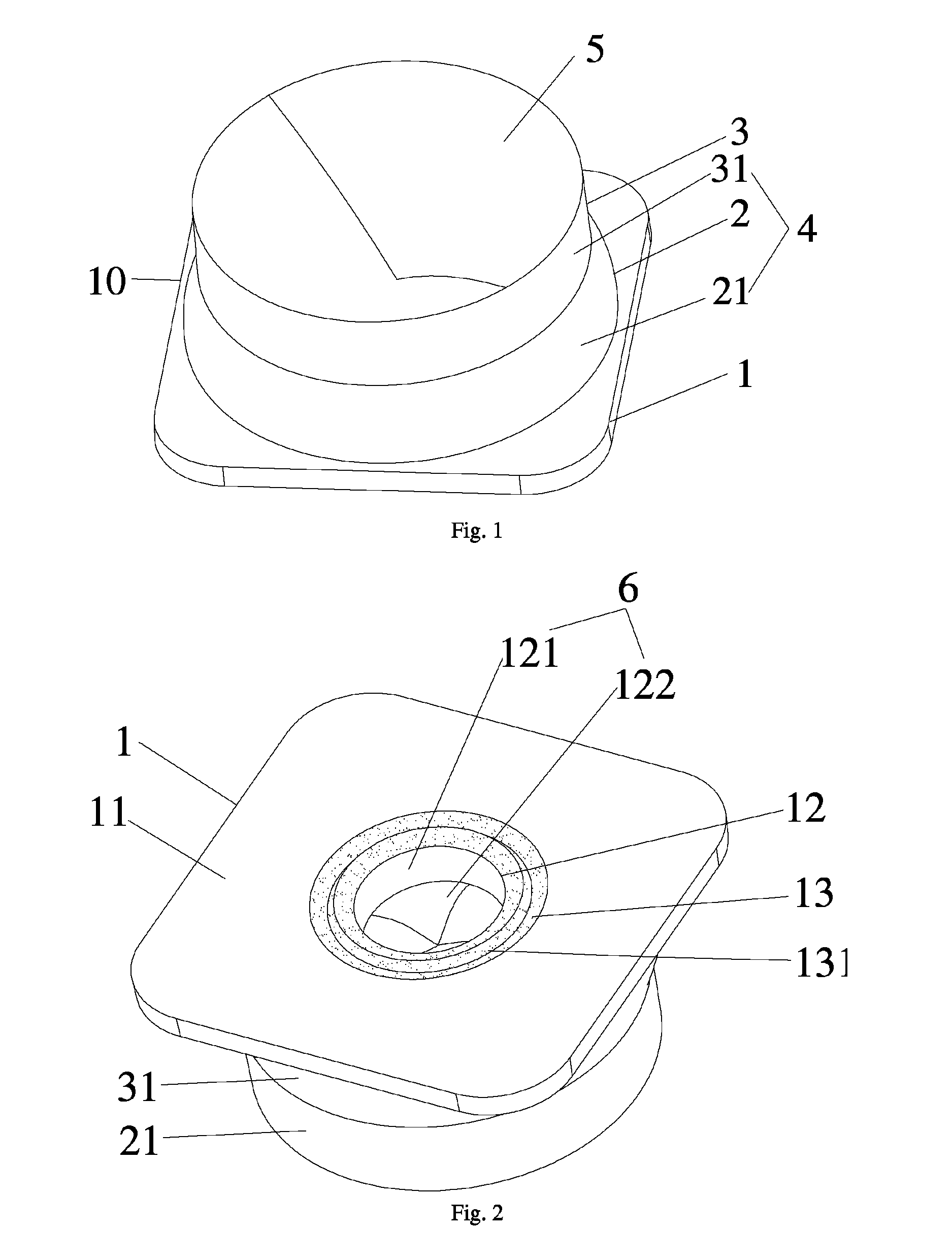
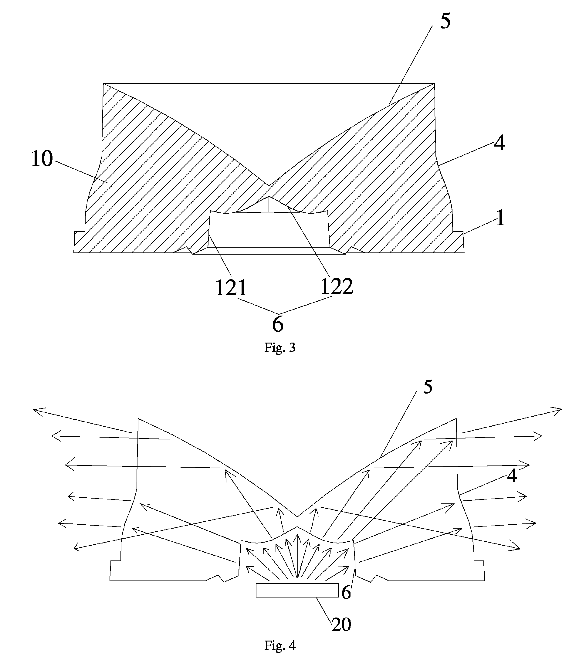
[0034]As shown in FIG. 1 to FIG. 4 of the example 1, the new LED lens 10, includes base stand 1, the first protruding stand 2 set on the base stand 1 and the second protruding stand 3 set on the first protruding stand 2; the side wall of the first protruding stand 21 and the side wall of the second protruding stand 31 constitute the exit surface 4, the side wall of the first protruding stand 21 is outside-protruding curved surface structure; the top surface of the second protruding stand is reflective surface 5, and the reflective surface 5 is conic concave structure; the bottom of the base stand 11 is set the cylindrical hole 12 for installing LED 20, and the surface of the cylindrical hole 12 constitutes incidence surface 6; the light from LED is irradiated inward from the incidence surface 6, and a part of the light is irradiated outward from the exit surface 4 after reflected by the reflective surface 5, and the other part of the light is irradiated from the exit surface 4 and t...

example 2

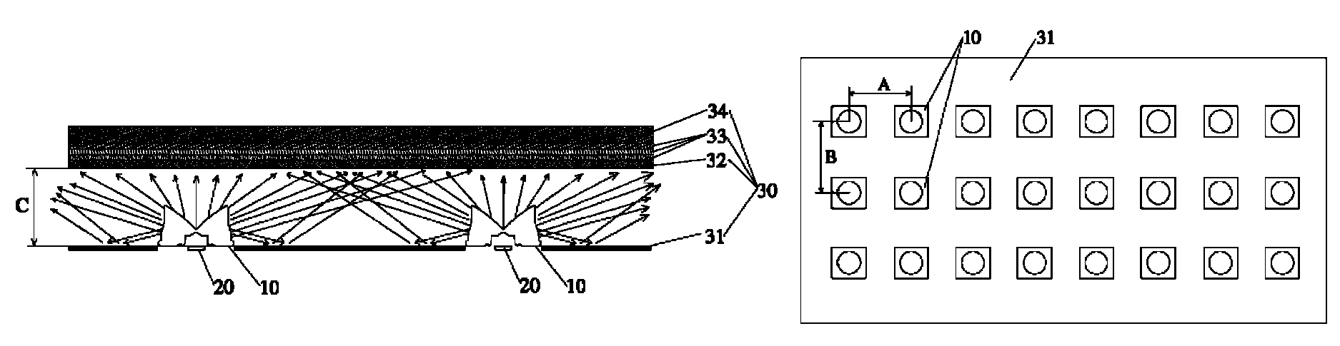
[0041]As shown in FIG. 6 and FIG. 7, the LCD backlight screen 30 of the example 2 includes the said new LED lens 10 of the example 1. And the example 2 also includes reflective membrane 31, scattering plate 32, brightness enhancing film 33, and LCD panel 34. And several the new LED lens 10 are set on the reflective membrane 31 and arranged as rectangular array, the row distance is A, and the line distance is B; the scattering plate 32 is above the reflective membrane 31 and the new LED lens 10, and the distance between the scattering plate 32 and reflective membrane 31 is C, the ratio of distance and height is

[0042]S=12×(A+B)C,

and S is more than or equal to 4.5. In the example, the brightness enhancing film 33 covers on the scattering plate 32, the LCD panel 34 covers on the scattering plate 32, and the quantity of the brightness enhancing film 33 is three layers but not limited to three layers, it can be increased or decreased as needed.

[0043]The other structures of the LCD backlig...


PUM

PropertyMeasurementUnit
distanceaaaaaaaaaa
heightaaaaaaaaaa
transparentaaaaaaaaaa

Abstract

The present invention discloses a new LED lens and LCD backlight screen thereof. The said new LED lens includes base stand, the first protruding stand set on the base stand and the second protruding stand set on the first protruding stand; the side wall of the first protruding stand and the side wall of the second protruding stand constitute the exit surface, the side wall of the first protruding stand is outside-protruding curved surface structure; the top surface of the second protruding stand is reflective surface, and the reflective surface is conic concave structure; the bottom of the base stand is set the cylindrical hole for installing LED, and the surface of the cylindrical hole constitutes incidence surface. The present invention achieves the intention of acquiring the same brightness degree through reducing the projection distance by half compared to the present refractive optical lens with the same LED arrangement distance.

Description

CROSS-REFERENCE TO RELATED APPLICATIONS[0001]This present application claims the benefit of Chinese Patent Application No. 201310420369.3 filed on Sep. 13, 2013; the contents of which are hereby incorporated by reference.FIELD[0002]The present invention relates to the technical field of LED (Light Emitting Diode) lens, particularly relates to new LED lens and LCD backlight screen.BACKGROUND ART[0003]LED light source has been widely used in the fields of illumination and LCD backlight screen due to its traits of energy saving and environmental protection. Especially it has been used in LCD backlight screen in large quantities, and has created wide social value and commercial value. It has mainly two arrangement ways of LED backlight source:[0004]1. Side-entering Mode: to achieve well-distributed brightness of screen by utilizing LED cooperated with light guide plate.[0005]2. Directly-entering Mode: to achieve well-distributed brightness of screen by utilizing LED cooperated with ligh...

Claims


Application Information

Patent Timeline
Patent Type & Authority Patents(United States)
IPC IPC(8): F21V5/00G02B19/00F21V5/04G02F1/1335
CPCF21V5/04G02B19/0028G02B19/0061G02F1/133603G02F1/133606G02F2001/133607G02F1/133607
Inventor JIANG, LIWANG
Owner DONGGUAN OUKE OPTOELECTRONICS TECH
Why Eureka
Try Eureka