Surgical clips with penetrating locking mechanism and non-slip clamping surfaces

a surgical clip and locking mechanism technology, applied in the field of surgical clips, can solve the problems of end fitting insecurely under intense strain, and achieve the effects of preventing dislodgment of the clip, stabilizing during use, and preventing undesirable angulation (angular disorientation)

Active Publication Date: 2016-03-15
TYCO HEALTHCARE GRP LP
View PDF9 Cites 156 Cited by
  • Summary
  • Abstract
  • Description
  • Claims
  • Application Information

AI Technical Summary

Benefits of technology

[0020]An alternative clip design includes one arm (either a female arm or a male arm) having a pair of elongated arms or spars separated by a space or gap. The gap between the spars receives an elongated wedge-shaped ridge projecting from the clamping surface of the opposite arm, when the arms are in a closed position. The gap is wide enough to allow at least a portion of the ridge and clamped tissue or vessel to fit within the gap, thus preventing dislodgment of the clip during extreme pressure circumstances. In another embodiment, one arm includes a central window.
[0021]An exemplary clip includes a plurality of bosses, including a hinge boss, for gripping by an applicator and stabilizing during use. As used herein, a boss is a projection or protuberance that can be engaged by an applicator. The hinge boss is a grippable boss (i.e., a protrusion suitable for gripping) at or near the hinge. Gripping the hinge boss during use prevents undesirable angulation (angular disorientation) of the clip during use with an applicator. An alternative design to prevent undesired angulation of the clip during use with the applicator is to have rectangular-shaped bosses near the free end of each arm. Rectangular-shaped bosses maintain the alignment of the clip within the arms of the applicator while it is applied onto tissue, preventing the proximal end of the clip (the hinge region) from angulating out of the jaws of the applicator.
[0022]In one embodiment, the clip has a width of about 3.2 mm or more, as compared to about 1.6 mm for prior art polymer ligation clips. This extra width provides several advantages—it provides a greater clamping surface area between the clamp arms; it permits a relatively large, wide, and strong male pin feature to penetrate tissue; and it permits a relatively large diameter female receptacle cross section with a larger aperture and retention area to secure the male feature.

Problems solved by technology

When thick tissue is clamped between the arms of the clip, the two arms will bow outward, causing the male and female ends to fit insecurely under intense strain—predisposing it to not close securely or “pop-open” once it is clamped closed.

Method used


Image

  • Surgical clips with penetrating locking mechanism and non-slip clamping surfaces
  • Surgical clips with penetrating locking mechanism and non-slip clamping surfaces
  • Surgical clips with penetrating locking mechanism and non-slip clamping surfaces

Examples


Embodiment Construction

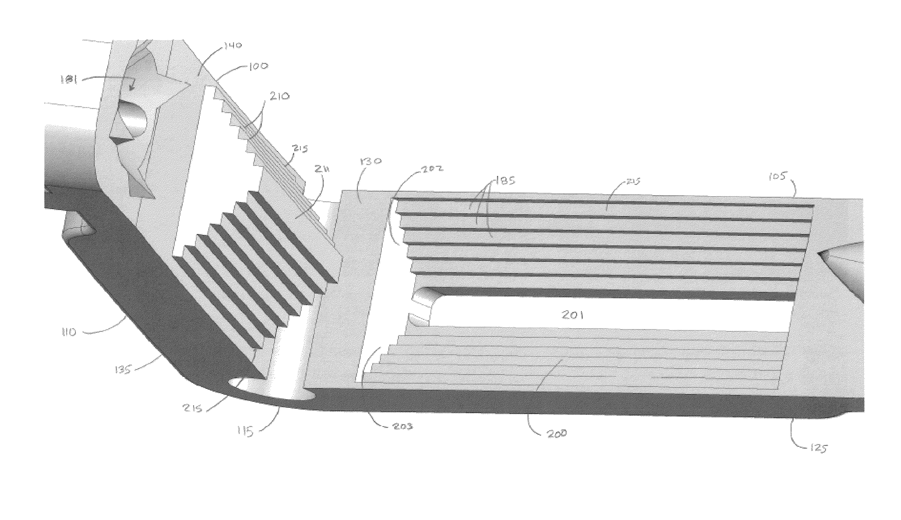
[0070]In one embodiment, ligating clips comprise a tissue-penetrating locking mechanism with an elongated receptacle, a configuration of slip-resisting grooves on the clamping surfaces, and a hinge lock.

Clip Arms

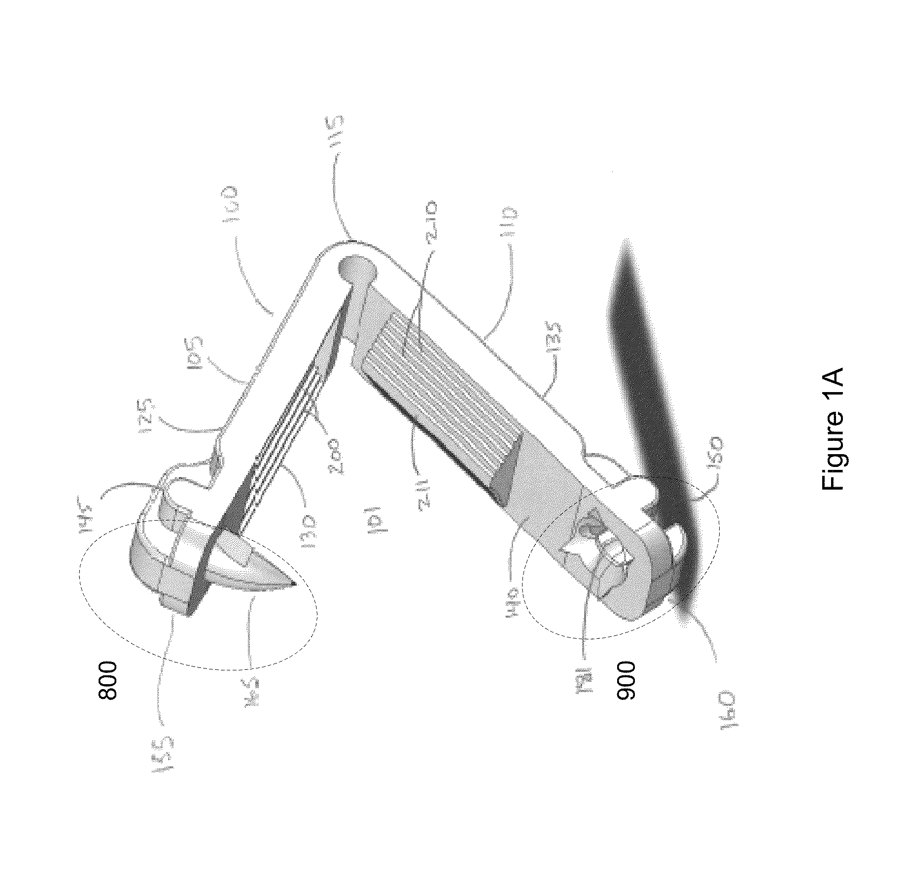
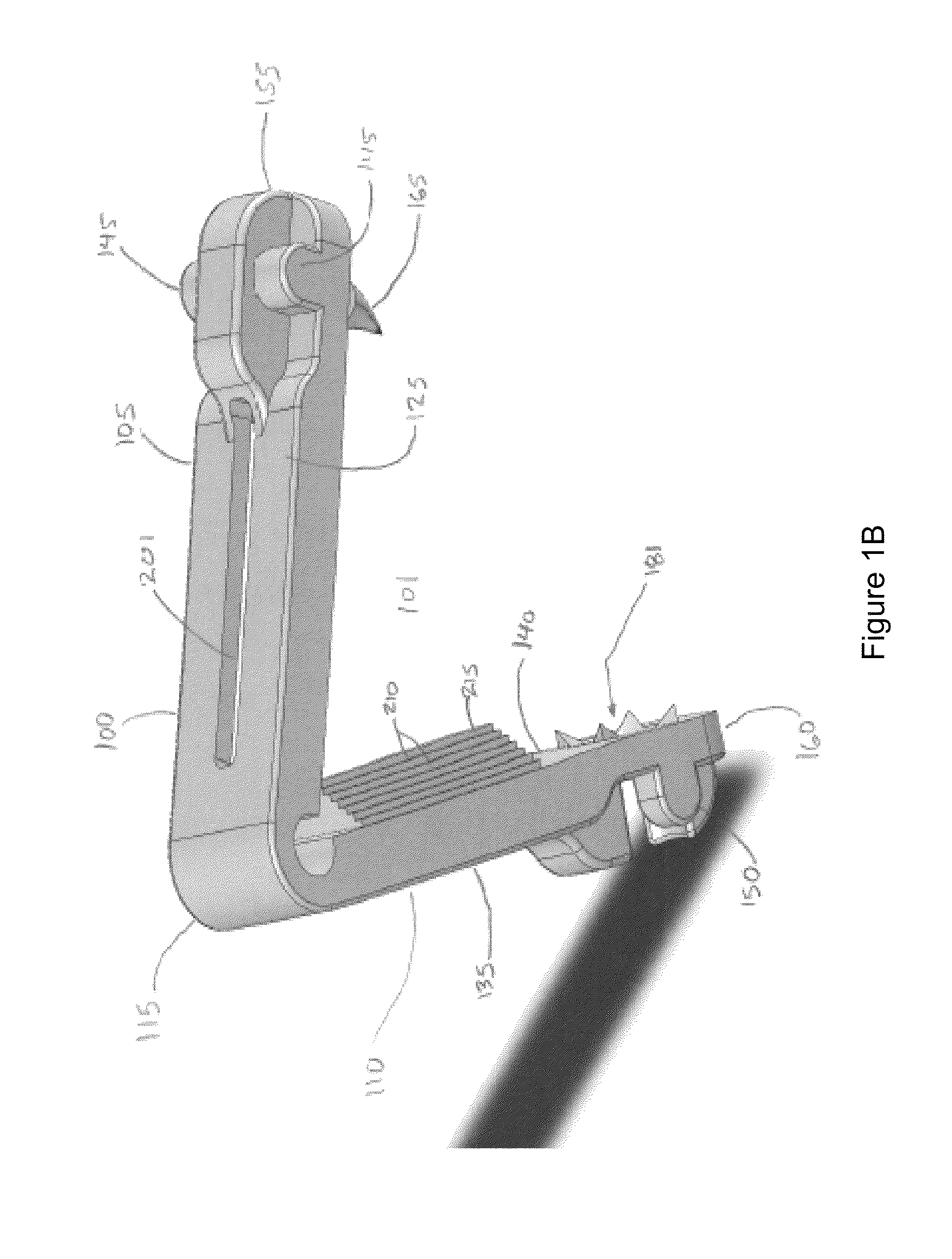
[0071]With reference to FIGS. 1A through 3, in one embodiment, a clip 100 according to principles of the invention generally includes a pair of clamping arms 105 and 110, adjoined at an integral flexible hinged joint 115 (the “hinge”), free at the other end 155, 160 and defining an opening 101 therebetween, such as an opening having a generally u- or v-shaped space. The opening 101 is preferably sufficiently wide to engage a vessel, organ or tissue to be ligated. In the exemplary embodiment shown in FIGS. 1A, 1B, 1C, the clamping arms 105, 110 are generally rigid. However, the hinged end 115 is sufficiently flexible so that the arms, 105, 110 can be angularly deflected bringing their free ends 155, 160 towards each other to decrease the space between the arms 105, 110, until...


PUM


Abstract

A surgical clip includes a pair of opposed arms joined at one end by an integrally formed flexible hinge and a hinge lock. A male locking pin near the free end of one arm is configured to penetrate tissue when the male locking pin is urged towards a mating female aperture near the end of the opposite arm. The clamping side of an arm may include a protruding feature, such as a wedge shape elongated ridge, while the clamping side of the opposite arm includes a corresponding trough or aperture that receives the protruding feature. Clamping surfaces may include non-slip protrusions, such as ribs, ridges, cones or pins. An applicator holding feature, such as a boss, near the hinge prevents the clip from yawing and becoming askew during application.

Description

RELATED APPLICATIONS[0001]This non-provisional U.S. patent application is related to U.S. Provisional Application No. 61 / 713,599 filed on Oct. 14, 2012, and claims the benefit of that filing date.FIELD OF THE INVENTION[0002]The present invention relates to surgical clips, and, more particularly, to a biocompatible surgical clip with grooved clamping surfaces to prevent slipping, a tissue penetrating head lock mechanism, and a locking hinge portion to provide greater tension and security when clamping tissue between the two arms of the clip.BACKGROUND[0003]A wide number of surgical procedures employ surgical clips (i.e., ligation clips). Such surgical procedures may require vessels, organs or other tissues of the human body to be ligated. Surgical clips ligate, clamp, close off or otherwise occlude the engaged portion of the clamped vessels, organs or other tissues in a surgical site. Such clips may also be used to secure the ends of a suture, as in place of a conventional suture kno...

Claims


Application Information

Patent Timeline
Patent Type & Authority Patents(United States)
IPC IPC(8): A61B17/08A61B17/122
CPCA61B17/122A61B17/1227A61B17/083A61B17/1285
Inventor PATEL, MANOJ B.PATEL, BHAILAL H.ALBALA, DAVID M.
Owner TYCO HEALTHCARE GRP LP
Why Eureka
Try Eureka