Method for improving rifle accuracy

a rifle and accuracy technology, applied in the field of rifle accuracy, can solve the problems that factory loaded ammunition can be shot at even very great distances with accuracys that have been previously unobtainable, and achieve the effect of increasing shooting accuracy

Active Publication Date: 2016-03-15
SELLARS TIMOTHY
View PDF28 Cites 24 Cited by
  • Summary
  • Abstract
  • Description
  • Claims
  • Application Information

AI Technical Summary

Benefits of technology

[0018]The method of the present invention is directed toward increasing the shooting accuracy achievable with rifles, and particularly when shooting a rifle at a given, fixed distance using ammunition of varying velocity, or under varying atmospheric conditions. By this means, it becomes possible to “match” the rifle to a particular ammunition. Thus, it is unnecessary to select a cartridge based upon the inherent responses of a particular rifle or the necessity of having the rifle barrel matched to a particular brand and / or velocity of ammunition. Accordingly, factory loaded ammunition can be shot at even very great distances with accuracies heretofore unobtainable. Moreover, different factory loaded cartridges can be fired accurately from the same rifle by merely making appropriate system adjustments.
[0019]The method of the invention thus provides a method of increasing rifle accuracy by converging bullet velocity to a given distance. To accomplish this purpose, a rifle is first provided with a stock having a butt section and a forearm section with a stock recess, an action / receiver with a front face and a rear face, a vertically depending recoil lug attached to the front face of the action and a one piece barrel having a barrel shoulder at one end which extends outwardly from the recoil lug and which has a distal, muzzle end. The barrel is mounted in free-floating fashion within the stock recess so that the barrel extends from the recoil lug and rifle action and so that nothing is touching between the stock and the barrel forward of the recoil lug. The rifle action is extended with a tensioning bar which is welded to the recoil lug, the tensioning bar extending in a generally horizontal plane outwardly from the recoil lug in the direction of the barrel. The rifle is also provided with an adjustment knob which extends vertically downward from the rifle forearm at one extent and which contacts the tensioning bar at an opposite extent. The adjustment knob can be adjusted between minimum and maximum positions, the maximum position serving to restrict the tendency of the action to lift up out of the stock recess under recoil.
[0020]The barrel is designed with certain specified characteristics. The barrel has a solid bull muzzle end with a recessed crown, the barrel weight which exists in front of the recessed crown being in tune for one specific distance only. Preferably, the barrel is cut to a specific length and muzzle weighted to tune the barrel to the longest expected shooting distance which is expected to be encountered. The barrel has a narrowed mid-section which produces an increased, “whippy” vertical bending action under recoil and a thus a wider tune spectrum on the vertical upswing of the barrel under recoil.
[0021]The tensioning bar and adjustment knob are incrementally adjusted to vary any muzzle weighted effect produced by the barrel design when shooting at shorter distances or when there is a velocity variance in the ammunition being used in the rifle. In a preferred embodiment of the invention, adjusting the tension on the tensioning bar with the adjustment knob between minimum and maximum positions acts to restrict movement of the action and, in turn, upward force on the barrel acting to lift the barrel upward from the stock recess, thereby reducing vertical whipping action of the barrel at shorter shooting distances or to compensate for variances in ammunition velocity. The barrel design, along with the tensioning bar and adjustment knob provide infinite tuning accuracy with varying velocity ammunition and in varying atmospheric conditions.
[0023]The inner core component has an internally threaded, barrel receiving end which receives and engages the exteriorly threaded end of the rifle barrel in overlapping fashion, an oppositely arranged exteriorly threaded end, and a central bore between the two ends which allows the passage of a bullet when the bullet is fired, firing of the bullet also setting off hot exhaust gases in the central bore. The sleeve component forms a surrounding outer chamber between the sleeve component and the inner core component when in place on the inner core component. The inner core component also has an inner chamber with at least one pair of oppositely facing window openings for exhausting gases from the inner chamber into the surrounding outer chamber. The inner core component also has an exterior longitudinal region forward of the central chamber, the exterior region having a series of longitudinally aligned, upwardly extending teeth formed therein for reducing the velocity of the hot gases contacting the upwardly extending teeth.
[0027]When the noise suppressor of the invention is used with the highly accurate rifle design of the invention, the noise suppressor adds weight forward of the crown of the rifle muzzle, the added weight being proportional to a desired tuning effect at a longest expected shooting distance, for positively compensating the rifle for slower bullet velocities.

Problems solved by technology

Accordingly, factory loaded ammunition can be shot at even very great distances with accuracies heretofore unobtainable.

Method used


Image

  • Method for improving rifle accuracy
  • Method for improving rifle accuracy
  • Method for improving rifle accuracy

Examples


Embodiment Construction

[0039]The preferred version of the invention presented in the following written description and the various features and advantageous details thereof are explained more fully with reference to the non-limiting examples included in the accompanying drawings and as detailed in the description which follows. Descriptions of well-known components and processes and manufacturing techniques are omitted so as to not unnecessarily obscure the principle features of the invention as described herein. The examples used in the description which follows are intended merely to facilitate an understanding of ways in which the invention may be practiced and to further enable those skilled in the art to practice the invention. Accordingly, the examples should not be construed as limiting the scope of the claimed invention.

[0040]Rifle Accuracy System:

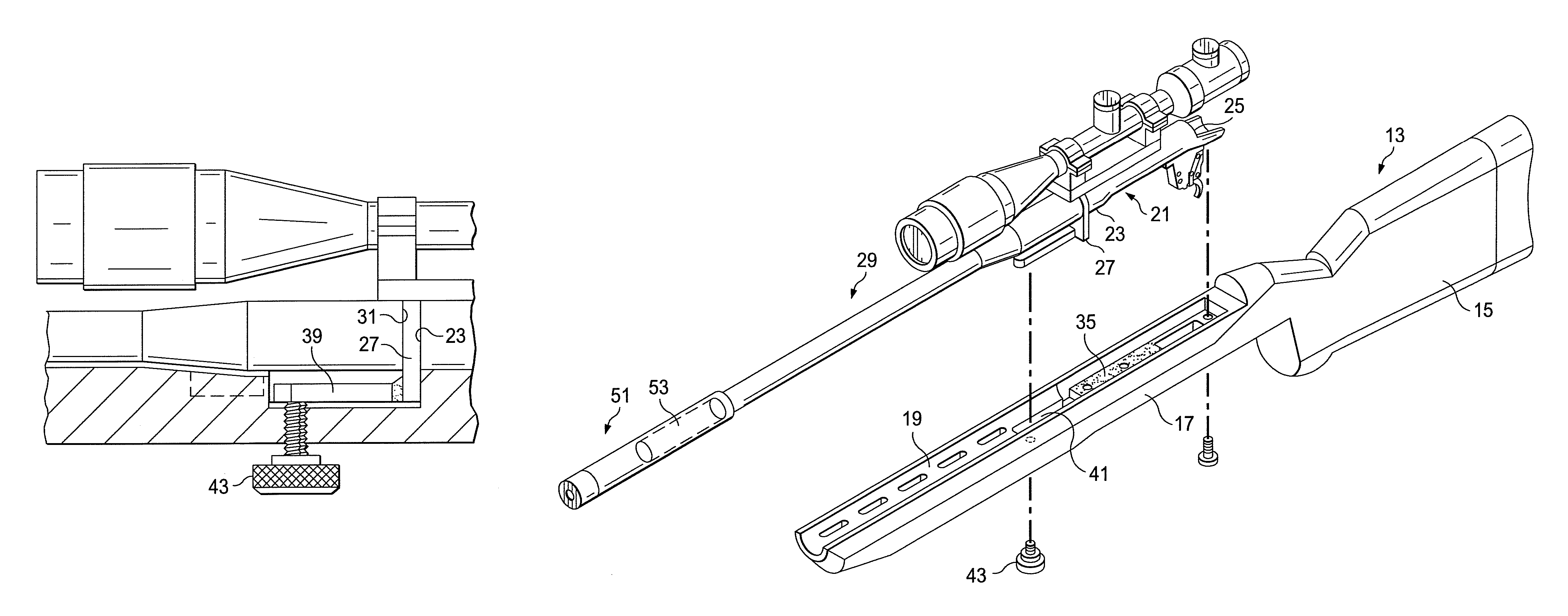
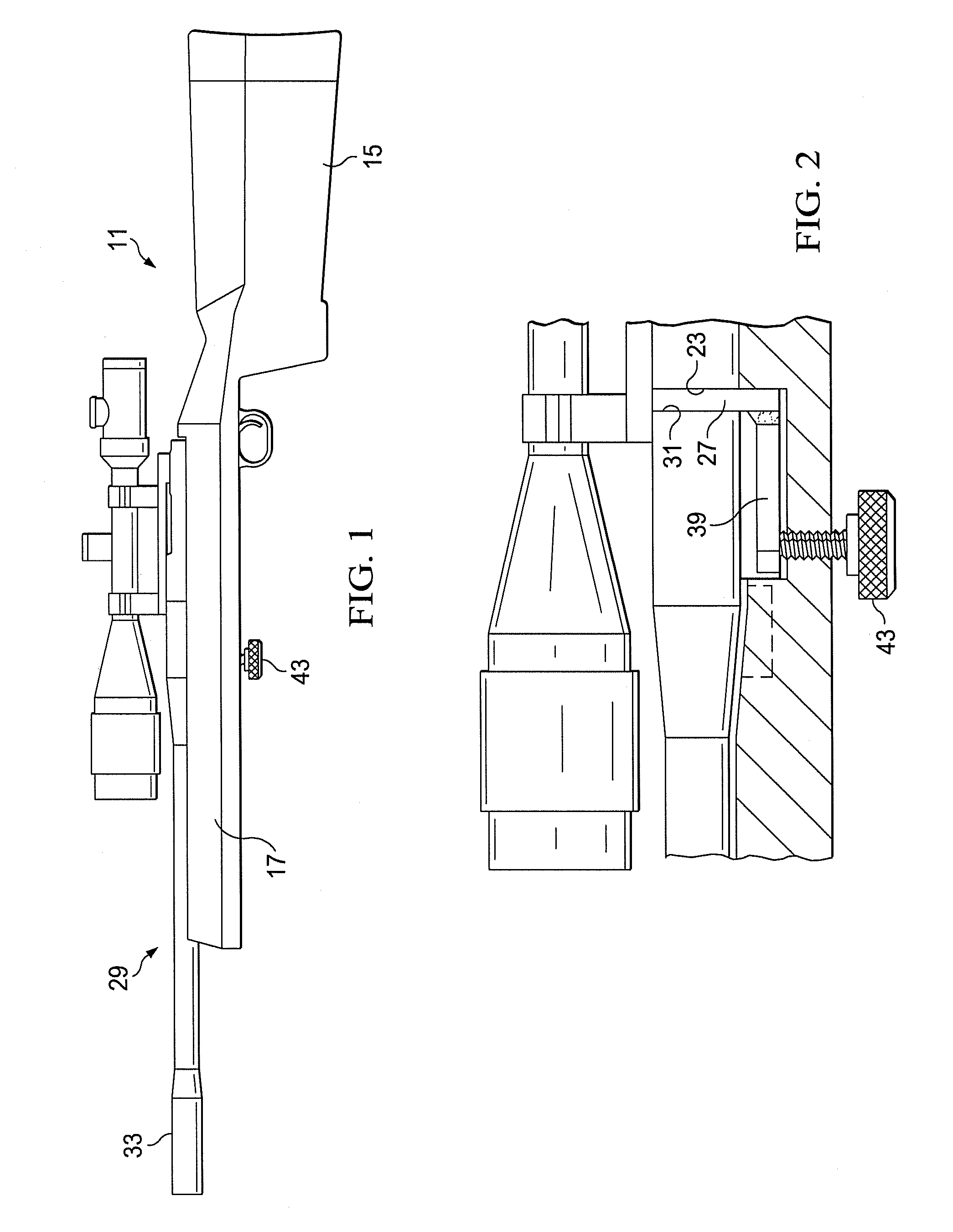
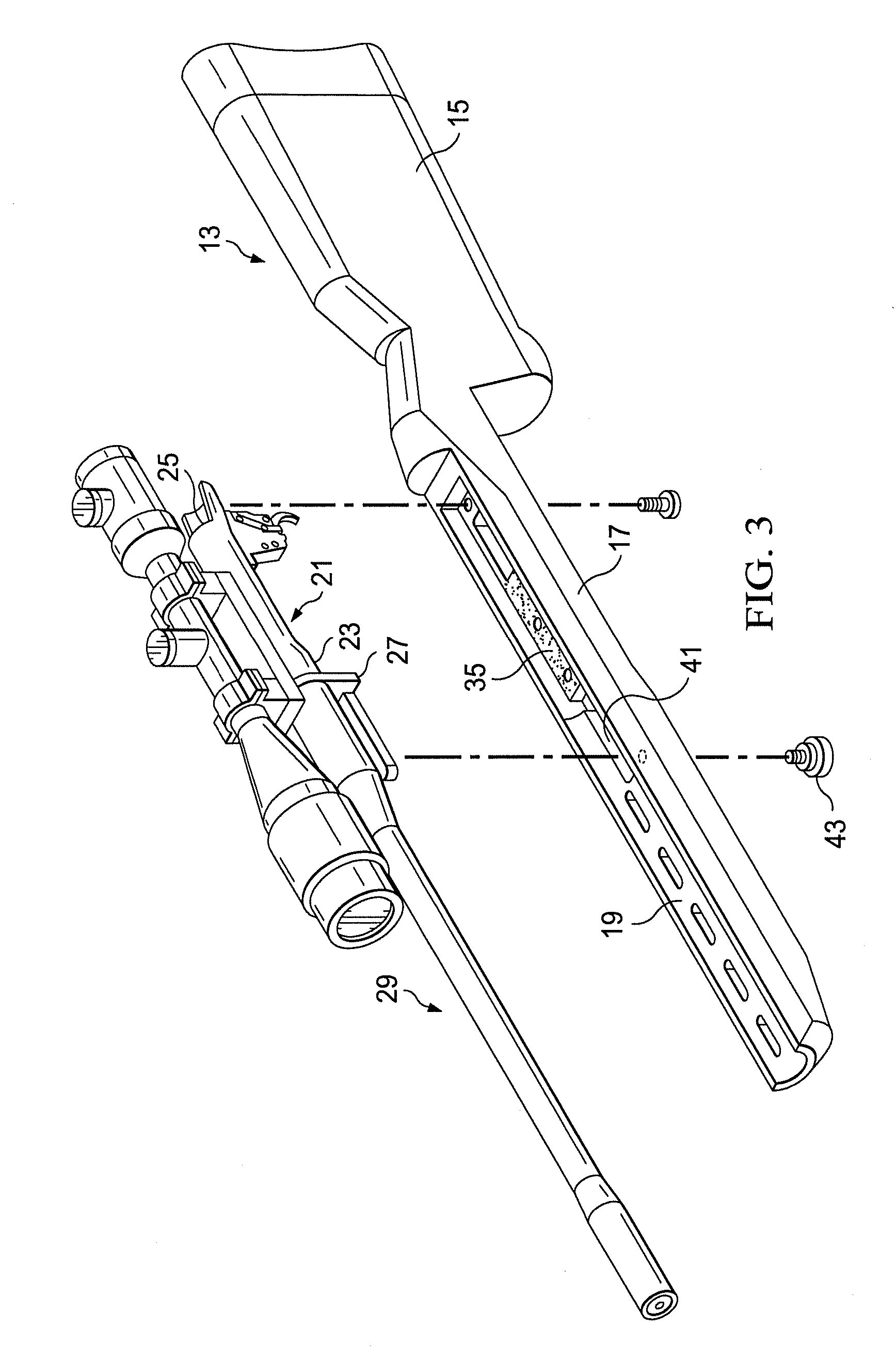
[0041]In a first aspect, the present invention deals with a rifle accuracy system which will now be described. Turning to FIG. 1, there is shown a rifle...


PUM


Abstract

A method is shown for increasing rifle accuracy. The rifle component parts are tuned for hitting a target at the same spot for a given fixed distance. The characteristics of the rifle barrel design give it an infinitely tunable positive compensation. The positive compensation characteristics of the rifle can be varied by adjusting a tensioning bar welded to the rifle recoil lug and an associated adjustment knob extending from the action to the exterior of the rifle stock. Increasing the tension on the tensioning bar reduces the upswing of the rifle barrel from the stock under the force of recoil.

Description

CROSS REFERENCE TO RELATED APPLICATIONS[0001]The present application claims priority from a previously filed provisional application, Ser. No. 61 / 862,288, filed Aug. 5, 2013, entitled “Method of Improving Rifle Accuracy”, by the same inventor.BACKGROUND OF THE INVENTION[0002]A. Field of the Invention[0003]The present invention relates generally to rifle accuracy and, more particularly, to a method for improving the accuracy of rifles when shooting at a fixed distance, using varying velocity ammunition and when shooting in differing atmospheric conditions. In another aspect, the invention relates to a noise suppressor design for such a rifle.[0004]B. Description of the Prior Art[0005]There has always been a desire among marksmen for firearms to be as accurate and consistent as possible during firing. This desire is particularly characteristic of marksmen who engage in rifle target shooting competitions and so-called “bench rest” competitions. As a result, the prior art is replete wit...

Claims


Application Information

Patent Timeline
Patent Type & Authority Patents(United States)
IPC IPC(8): F41A21/48F41A3/64F41A21/30F41A3/66F41C23/00
CPCF41A21/30F41A3/64F41A3/66F41A21/48F41A21/485F41C23/00
Inventor SELLARS, TIMOTHY
Owner SELLARS TIMOTHY
Why Eureka
Try Eureka