Speeding enforcement method of vehicle using wireless communications

a wireless communication and speeding technology, applied in road vehicle traffic control, traffic movement detection, instruments, etc., can solve the problems of high accident risk, large accident risk, and high cost of loop detectors used in speed enforcement methods as described above, and achieve the effect of reducing costs

Active Publication Date: 2016-03-15
HL KLEMOVE CORP
View PDF17 Cites 1 Cited by
  • Summary
  • Abstract
  • Description
  • Claims
  • Application Information

AI Technical Summary

Benefits of technology

[0011]An object of the present invention is to provide a vehicle speed enforcement method capable of identifying a speed of a vehicle in real time and reducing cost necessary for speed enforcement.
[0022]The vehicle speed enforcement method according to the present invention has an advantage in that the overspeed of a vehicle can also be measured outside a non-detection zone because the speed of the vehicle can be identified in real time.
[0023]In addition, there is an advantage in that installation and maintenance costs of a device for use in speed enforcement are low.
[0024]In addition, there is an advantage in that information about a vehicle can be received using multi-hop technology even in a location outside a communication range.

Problems solved by technology

These conventional speed enforcement methods have a disadvantage in that the effect of speed enforcement is substantially small because many drivers usually maintain a legal speed only in a detection zone due to enforcement only in a specific zone and run at a speed exceeding the legal speed in a non-detection zone.
In addition, in this case, there is a problem in that the danger of accident is great because drivers tend to suddenly reduce their vehicle speeds in the non-detection zone.
Also, because a device such as the loop detector used in the speed enforcement method as described above is very expensive, there is a problem in that initial installation cost and maintenance cost are high.

Method used


Image

  • Speeding enforcement method of vehicle using wireless communications
  • Speeding enforcement method of vehicle using wireless communications
  • Speeding enforcement method of vehicle using wireless communications

Examples


Embodiment Construction

[0031]Hereinafter, a vehicle speed enforcement method according to the present invention will be described in detail with reference to the drawings.

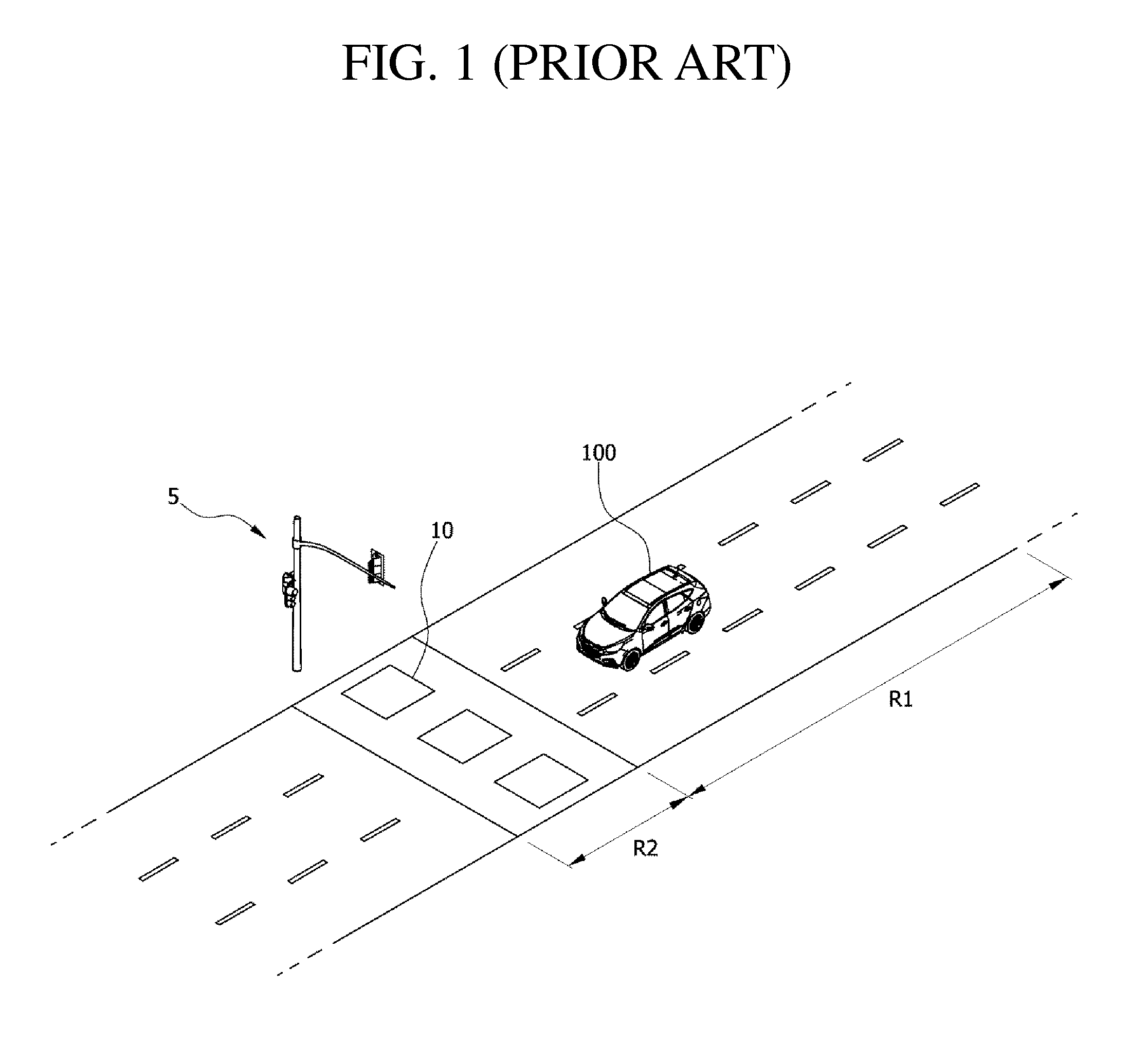
[0032]FIG. 1 is a diagram illustrating a conventional vehicle speed enforcement method.

[0033]In FIG. 1, the most widely used speed enforcement method in the conventional art is illustrated. Referring to FIG. 1, the measurement of a speed is not performed when a vehicle 100 runs in a non-detection zone R1. In addition, when the vehicle 100 passes through a detection zone R2, a loop detector 10 buried under the road identifies a vehicle entrance time point and a vehicle passage time point to measure the speed of the vehicle. At this time, when the speed of the vehicle is higher than the legal speed, a photo system 5 shoots the vehicle.

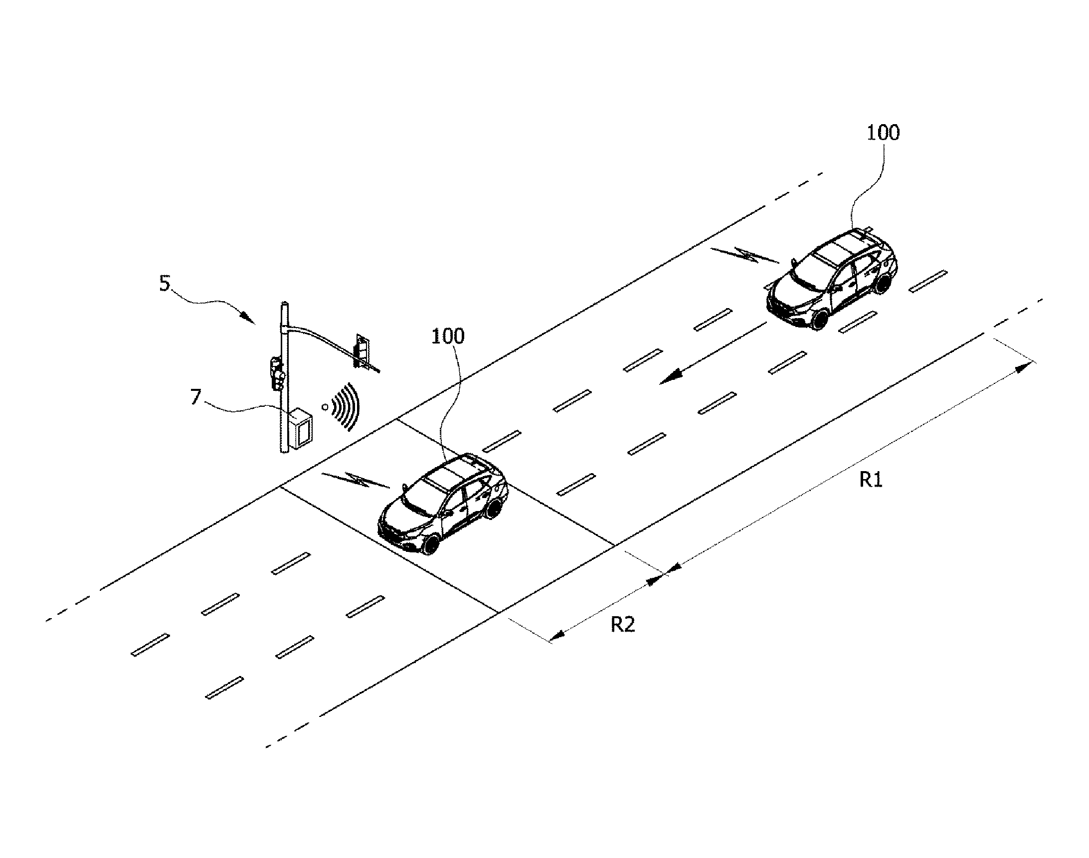
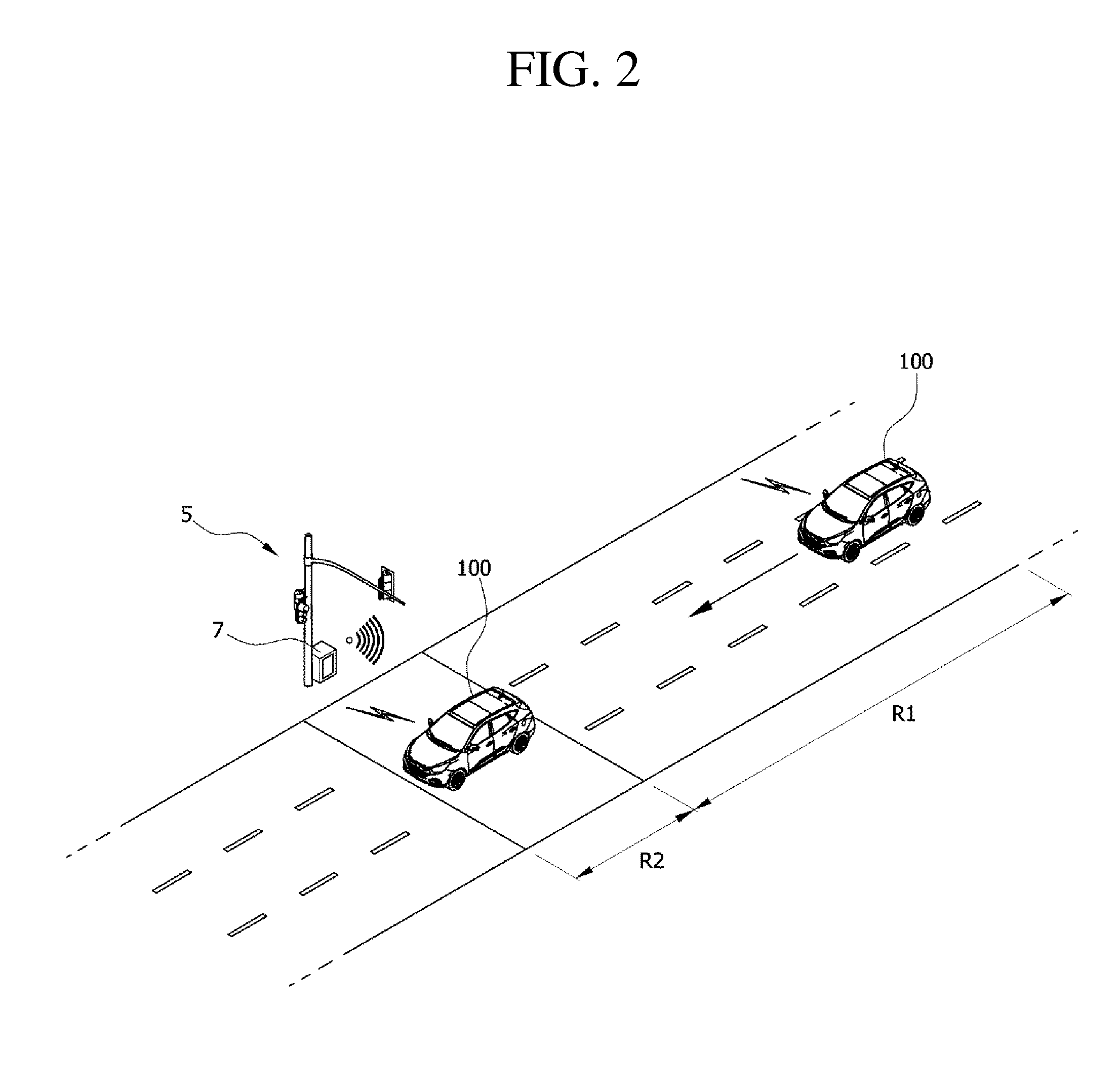
[0034]FIG. 2 is a diagram illustrating a state in which a target vehicle 100 runs in a non-detection zone R1 and a detection zone R2 in a vehicle speed enforcement method according to a first exemplary embodi...


PUM


Abstract

A vehicle speed enforcement method includes the steps of receiving and collecting, by a base station located in a detection zone, information about a target vehicle from a communication unit in the target vehicle, detecting a speed of the target vehicle through the collected information about the target vehicle, and setting the target vehicle as an overspeed vehicle when the speed of the target vehicle is faster than a reference limit speed at a point in time at which the target vehicle has entered the detection zone.

Description

BACKGROUND OF THE INVENTION[0001]1. Field of the Invention[0002]The present invention relates to a speed enforcement method of performing speed enforcement by measuring the speed of a vehicle, and more particularly to a speed enforcement method of performing vehicle speed enforcement using wireless communication.[0003]2. Description of Related Art[0004]Recently, various speed enforcement methods have been performed. Methods for more accurate and reasonable overspeed measurement have been constantly devised.[0005]A loop detector, a camera detector, and a radar detector are representative as the most widely used method. The loop detector detects and amplifies a small change amount in inductance generated by a vehicle passing on loop coil sensors to measure the presence and speed of the vehicle by burying and connecting two loop coil sensors per lane on an asphalt road surface. In addition, the camera detector measures and analyzes the traffic volume of vehicles traveling on a road in ...

Claims


Application Information

Patent Timeline
Patent Type & Authority Patents(United States)
IPC IPC(8): G08G1/01G08G1/052
CPCG08G1/052G08G1/01
Inventor KIM, JEE, HOON
Owner HL KLEMOVE CORP
Why Eureka
Try Eureka