Casing for electric connector coupled to a cable

a technology of electric connectors and casings, applied in the direction of electrical apparatus casings/cabinets/drawers, couplings, coupling devices, etc., can solve the problems of water penetration and inability to uniformly compress, and achieve the effect of uniform sealing performan

Inactive Publication Date: 2016-03-15
DAIICHI SEIKO CO LTD
View PDF28 Cites 2 Cited by
  • Summary
  • Abstract
  • Description
  • Claims
  • Application Information

AI Technical Summary

Benefits of technology

[0010]In view of the above-mentioned problem in the conventional electric connector, it is an object of the present invention to provide a casing used for an electric connector, capable of preventing the electric connector from deviating in position from an opening of the casing into which the electric connector is to be fit, to thereby ensure uniform sealing performance brought by a seal.
[0015]It is possible to position the electric connector relative to the opening in the first direction merely by bringing the electric connector into a contact with the pillar.
[0017]It is possible to position the electric connector relative to the opening in the first direction merely by inserting the electric connector into a space formed between the pillars.
[0024]It is preferable that each of the third surfaces includes a tapered portion causing a distance between the third surfaces to be smaller towards the opening from inside of the casing.
[0032]In the casing in accordance with the present invention, the first positioning unit positions an electric connector relative to the opening in a first direction defined as a length-wise direction of the wall, and the second positioning unit positions the electric connector relative to the opening in a height-wise direction of the wall. Thus, it is possible to prevent the electric connector from deviating in position from the opening of the casing into which the electric connector is to be fit, to thereby ensure uniform sealing performance provided by a seal.

Problems solved by technology

However, if the electric connector 1000 were fixed to the casing 1001 in such a condition that the electric connector 1000 inclines relative to the cylindrical portion 1003, the seal 1008 cannot be uniformly compressed due to the inaccuracy in a positional relation between the electric connector 1000 and the casing 1001, resulting in that it is likely that water penetrates the electric connector 1000 through an insufficiently compressed portion of the seal 1008.

Method used


Image

  • Casing for electric connector coupled to a cable
  • Casing for electric connector coupled to a cable
  • Casing for electric connector coupled to a cable

Examples


Embodiment Construction

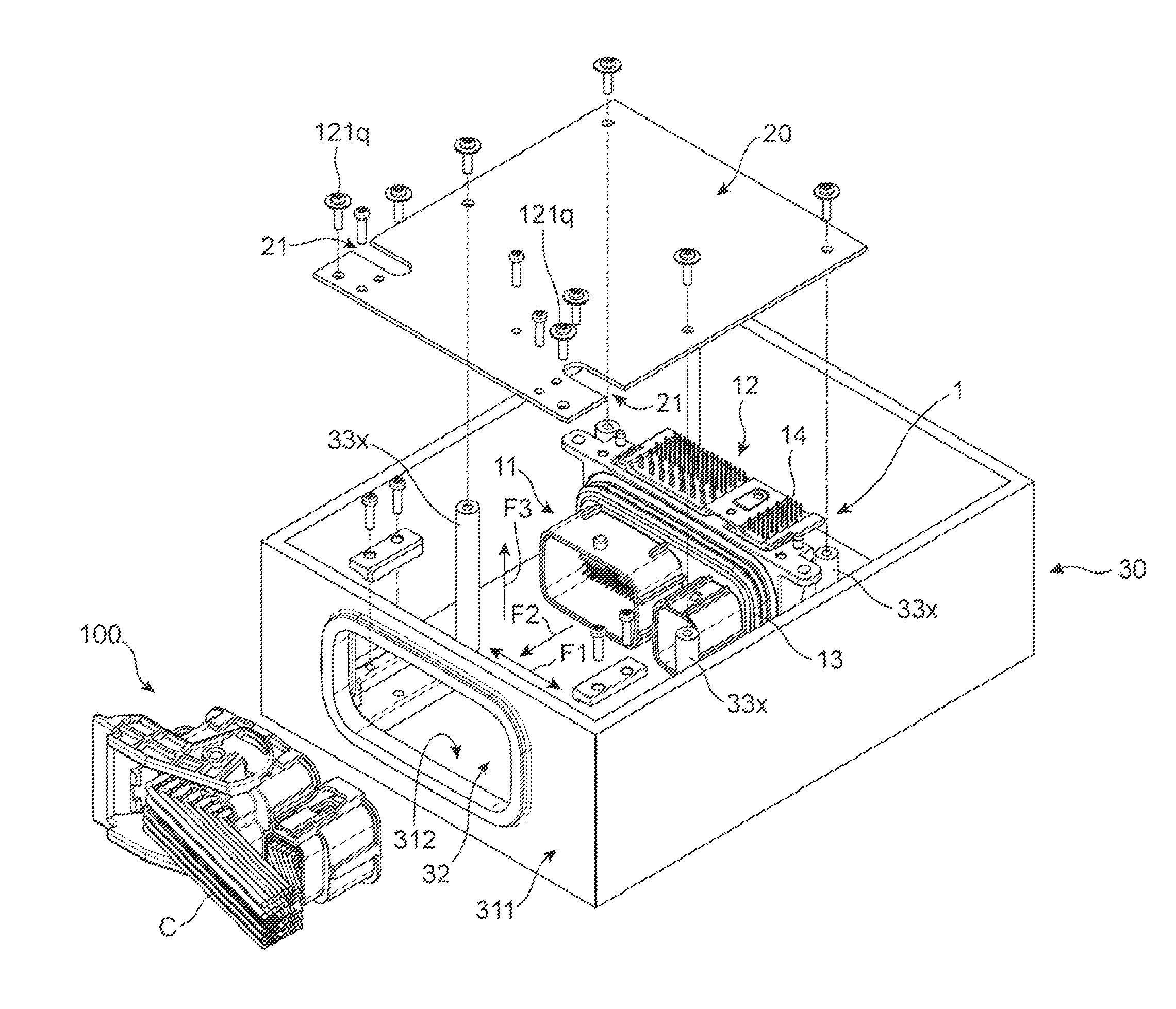
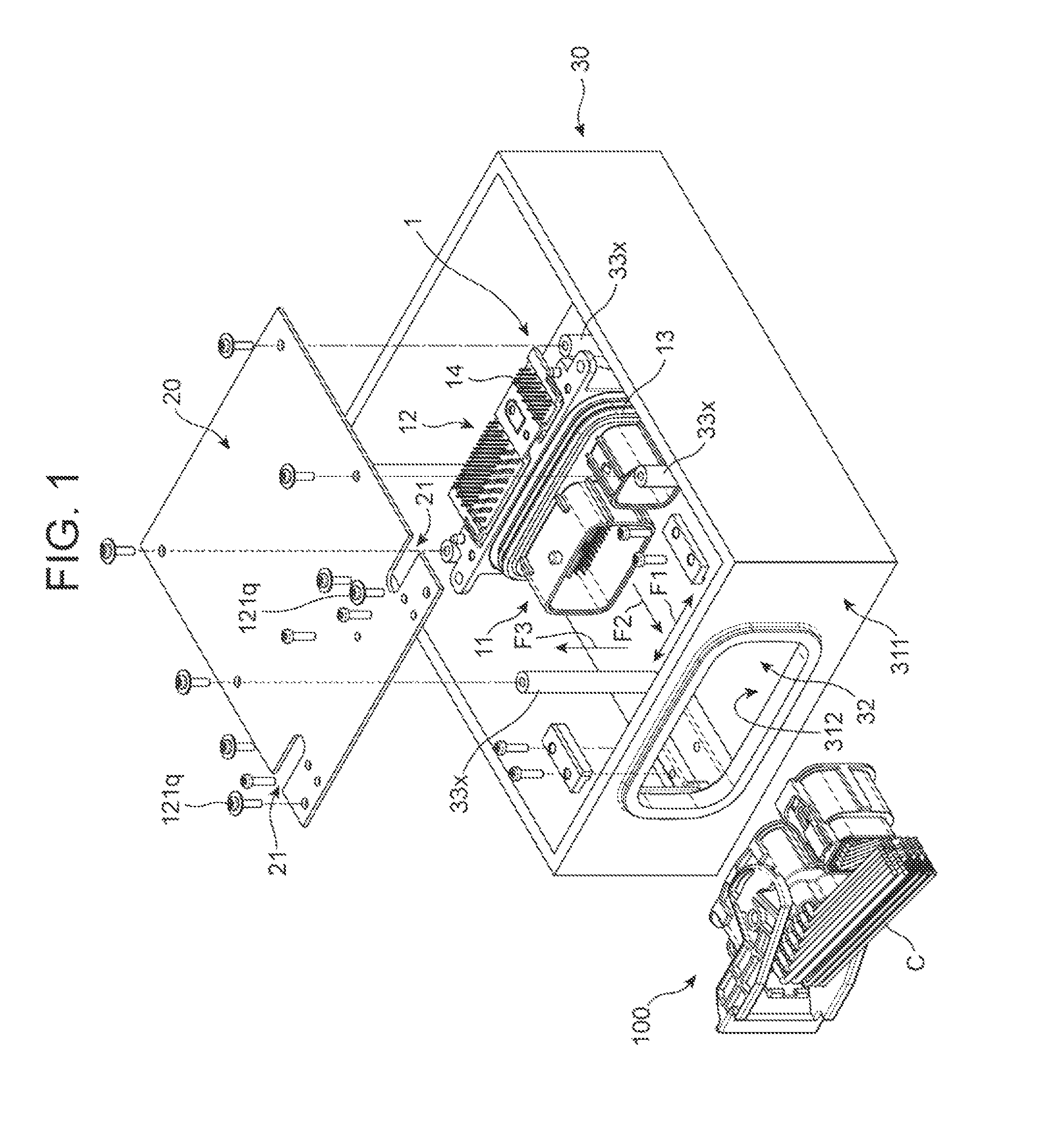
[0049]The preferred embodiment in accordance with the present invention is explained hereinbelow with reference to drawings. In the specification, a “front” of the electric connector indicates a side of the electric connector through which the electric connector is connected to the second electric connector, a “rear” of the electric connector indicates a side opposite to a “front”, a “lower” indicates a direction from the electric connector to a floor of the casing, and an “upper” indicates a direction opposite to a “lower”.

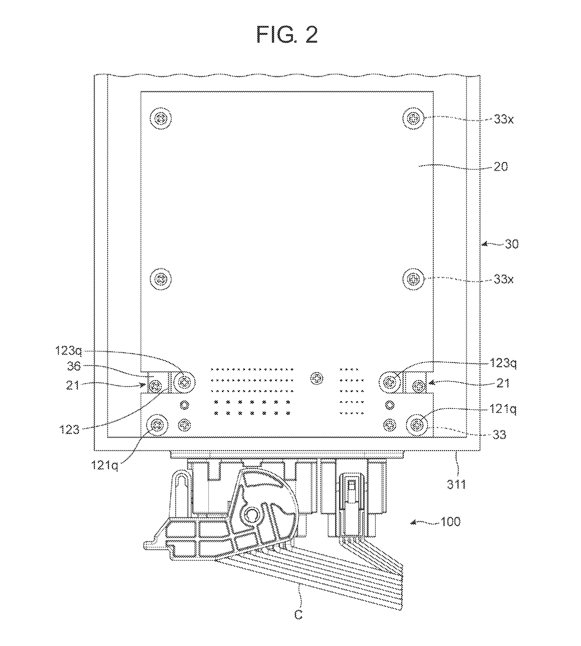
[0050]As illustrated in FIGS. 1 to 4, an electric connector 1 is mounted on a printed circuit board 20, housed in a casing 30, and then, connected to a second electric connector 100 to which a cable C is connected. The casing 30 is in the form of a box (a cover thereof is not illustrated).

[0051]As illustrated in FIG. 4, the casing 30 includes at least a floor 312, and a front wall 311 standing at a front edge of the floor 312 perpendicularly to the floor 312. The...


PUM

PropertyMeasurementUnit
lengthaaaaaaaaaa
heightaaaaaaaaaa
distanceaaaaaaaaaa

Abstract

A casing in which an electric connector is housed, including a floor, and a wall standing perpendicular to the floor, the wall being formed with an opening, when a part of the electric connector projects outwardly through the opening, a seal formed around the part making close contact with an inner edge of the opening, the casing further including a first positioning unit for positioning the electric connector relative to the opening in a first direction defined as a length-wise direction of the wall, and a second positioning unit for positioning the electric connector relative to the opening in a height-wise direction of the wall.

Description

BACKGROUND OF THE INVENTION[0001]1. Field of the Invention[0002]The invention relates to a casing used for an electric connector, and further to an electric connector to be used in combination with the casing.[0003]2. Description of the Related Art[0004]A kind of an electric connector is housed in a casing, and is coupled with a second electric connector connected to a cable. The electric connector includes a fitting portion through which the electric connector is coupled with the second electric connector. The fitting portion generally extends outwardly through an opening formed with the casing. Accordingly, the electric connector, in particular an electric connector to be equipped in an automobile, is generally designed to include a seal making close contact with the opening for the purpose of waterproofness.[0005]An electric connector as mentioned above is suggested in Japanese Patent Application Publication No. 2001-345153.[0006]FIG. 13 is a cross-sectional view of the electric ...

Claims


Application Information

Patent Timeline
Patent Type & Authority Patents(United States)
IPC IPC(8): H01R12/00H01R13/60H01R13/516H05K5/00H01R13/52
CPCH01R13/516H01R13/5202H01R13/60H05K5/0069Y10T29/49826H01R2201/26H01R12/724H01R13/748H01R13/52H01R13/5205H01R13/5208H01R13/521H01R13/5213H01R13/5216H01R13/5219H01R12/00
Inventor ENDO, TAKAYOSHIYAGI, SAKAIJINNOUCHI, SHOGOHAMACHI, HISASHI
Owner DAIICHI SEIKO CO LTD
Why Eureka
Try Eureka