Vehicle wheel spoke connection

a technology for spoke connections and vehicles, applied in the direction of spoked wheels, vehicle components, rims, etc., can solve the problems of increasing stress, flexing and creeping of relatively weak spoke connections, and low strength of materials compared to stronger materials that are more rigid and less, etc., to achieve easy installation, clean appearance, and economic production.

Active Publication Date: 2016-03-22
SCHLANGER RAPHAEL
View PDF13 Cites 28 Cited by
  • Summary
  • Abstract
  • Description
  • Claims
  • Application Information

AI Technical Summary

Benefits of technology

[0012]It is an object of the present invention to create a spoke connection: that may be blindly installed with the spoke bed of the rim and / or hub: that may leave the tire bed of the rim to remain unpierced; that may eliminate the necessity of a rim strip; that may permit a spoke connection that may otherwise be geometrically impossible by conventional means; and that may result in a robust connection capable of resisting spoke tension loads.
[0017]The present invention provides a spoke connection that may be blindly installed in the spoke bed. The connector may be economically produced using conventional manufacturing methods. The connection is easy to install and is serviceable in the field. The connection may be designed to provide a clean appearance with enhanced aesthetics. The connector may be made of high strength material(s), such as fiber-reinforced plastic or metals. The connector may have a large overlap with the spoke bed for increased robustness of the connection. The connector may be designed to minimize the size of the hole in the spoke bed, thereby increasing the strength of the bracing element (i.e. rim or hub). The connector may eliminate the necessity of a rim strip or rim tape. The resulting spoke connection is exceptionally robust and supports substantial spoke tension forces.
[0018]In contrast to prior art UK Patent Application GB2479870A by Jonathan Thulbon the connecting element of the present invention is comprised of two or more discreet segments. These segments are not required to flex during installation with the spoke bed and thus may be constructed of stronger and stiffer material (such as fiber reinforced polymer or metal) for increased robustness of the spoke connection. Further, since the segments are discreet, they may be installed in the spoke bed in sequential assembly steps, where each segment is installed in separate assembly steps. This permits the segment to include a comparatively larger lateral overhang surface and a correspondingly larger lateral depth of lateral overlap and engagement between the connecting element and spoke bed, thus reducing stresses at this interface and further strengthening the spoke connection. Still further, the overlie engagement between the spoke (or an intermediate connecting element connected to the spoke) and the connecting element may be located longitudinally outwardly from the outboard surface of the spoke bed, which does not require any longitudinally outward extension portions. This permits the corresponding hole in his spoke bed to be comparatively smaller. This smaller hole serves to further strengthen the spoke bed in this highly-loaded area. Yet further, the lack of such extension portions also serves minimize the tensile and bending stress on the connecting element due to spoke tension forces, further strengthening the spoke connection. Further still, the option of a longitudinal engagement permits a comparatively larger surface area of engagement than a single engagement location, which reduces stresses on the connector and spoke and allows for a minimized connector geometry, which requires a smaller hole in the spoke bed.

Problems solved by technology

However, such material generally has low strength in comparison to stronger materials that are more rigid and less ductile, such as metals or fiber-reinforced plastics that would not be able to flex as Thurbon requires.
Since spoke tension forces exert a very high stress at its connection to the rim, the weaker material of the Thulbon eyelet results in a relatively weak spoke connection that may also be more prone to flex and creep.
Second, since Thulbon's eyelet is of one-piece design, the entire eyelet must be inserted at one time.
As such, Thulbon's design is limited to a relatively shallow depth of lateral overlap and engagement between his eyelet and his rim, thus increasing stresses at this interface and further weakening his spoke connection.
This offset places additional tensile and bending stress on the eyelet due to spoke tension forces, further weakening his spoke connection.
Such a single overlie engagement requires a very large laterally projected area of overlie to resist spoke tension loads, which results in a larger eyelet and a correspondingly larger hole in his rim.

Method used


Image

  • Vehicle wheel spoke connection
  • Vehicle wheel spoke connection
  • Vehicle wheel spoke connection

Examples


Embodiment Construction

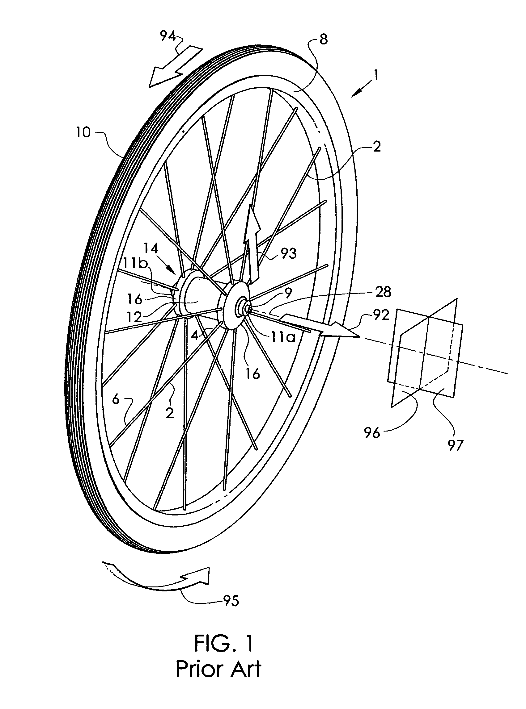
[0074]FIG. 1 describes the basic configuration of an exemplary prior art vehicle wheel, in particular, a bicycle wheel 1, as well as a description of the direction conventions used throughout this disclosure. For clarity, the frame and the quick release skewer assembly are not shown in this figure. The hub shell 14 is rotatable about the axle 9 and includes at least two axially spaced hub flanges 16, each of which include a means for connecting with the spokes 2. Axle 9 includes end faces 11a and 11b that define the spacing of its mounting with the frame (not shown). The axial axis 28 is the axial centerline of rotation of the bicycle wheel 1. The hub flange 16 may be contiguous with the hub shell 14 or it may be separately formed and assembled to the hub body 12 portion of the hub shell 14. The spokes 2 are affixed to the hub flange 16 at their first end 4 and extend to attach the rim 8 at their second end 6. The tire 10 is fitted to the outer periphery of the rim 8. The wheel of F...


PUM


Abstract

A vehicle wheel, comprising a rim, a hub, a plurality of spokes extending between the rim and hub, a bracing element including a hole with a central axis, a sidewall, a longitudinally inward entrance, and at least one of an engagement surface and an engagement edge outward of the entrance, a connecting element comprising a multiplicity of discreet segments. The bracing element comprises at least a portion of one of the rim and hub. At least one segment includes a laterally projecting overhanging surface. The first segment is positioned within the hole, with the overhang surface overlying one of the engagement surface and engagement edge in an overlie engagement. The second segment is positioned within the hole to include an opening between the first and second segments. The spoke is positioned within the opening and is connected to the connecting element with the overlie engagement to support spoke tensile load.

Description

CROSS-REFERENCE TO RELATED APPLICATION[0001]This application claims priority of the following U.S. provisional patent applications:[0002]61 / 575,380, filed Aug. 19, 2011, and entitled “VEHICLE WHEEL SPOKE CONNECTION”;[0003]61 / 575,381, filed Aug. 19, 2011, and entitled “VEHICLE WHEEL SPOKE CONNECTION”; and[0004]61 / 575,374, filed Aug. 19, 2011, and entitled “VEHICLE WHEEL SPOKE CONNECTION”.BACKGROUND OF THE INVENTION[0005](1) Field of the Invention[0006]This invention is related to the means of attachment between the spoke and the rim of a vehicle wheel and between the spoke and the hub of a vehicle wheel. This invention is particularly related to the connection of a spoke with a rim structure having a “double-wall” construction with an unpierced tire bed wall for tubeless tire applications.[0007](2) Description of the Related Art[0008]Bicycle wheel rims have historically been constructed to accept pneumatic tires that are designed to work in conjunction with an inner tube. This is the...

Claims


Application Information

Patent Timeline
Patent Type & Authority Patents(United States)
IPC IPC(8): B60B1/04B60B21/06
CPCB60B1/045B60B1/041B60B21/062B60B2900/113B60B2900/311
Inventor SCHLANGER, RAPHAEL
Owner SCHLANGER RAPHAEL
Why Eureka
Try Eureka