Three-dimensional woven corner fitting with lap joint preforms

a three-dimensional, lap joint technology, applied in the field of three-dimensional woven preforms, can solve the problems of not having the same materials or comparable physical, chemical, thermal or other properties, limiting the ability of the preform to transfer and bear the stress applied to the finished component, and cannot be formed into corner fittings withou

Active Publication Date: 2016-03-22
ALBANY ENGINEERED COMPOSITES
View PDF25 Cites 3 Cited by
  • Summary
  • Abstract
  • Description
  • Claims
  • Application Information

AI Technical Summary

Benefits of technology

[0013]Accordingly, the present invention relates to a 3D woven preform and a method of making a 3D woven preform which can be formed into a corner fitting without darting the legs or requiring additional reinforcing materials.
[0025]In this embodiment, the overlap region of the legs forms a double lap shear joint and, if the three woven layers in the leg segments are of equal thickness, the overlap region is of substantially the same thickness as the non-overlap portions of the leg. A double lap shear joint may have desirable properties for some applications. Some embodiments provide an overlap region having the same thickness as the non-overlap regions of the leg, in which the overlap portion is substantially coplanar with at least the immediately adjacent portion of the leg, and eccentric loading of the overlap region may be reduced over other types of overlap joints.
[0031]In embodiments of a 3D woven Pi preform with trifurcated (or bifurcated, or both) legs folded into the desired corner fitting shape in which one inner woven layer of a segment is interleaved between two woven layers of a second segment, a double lap joint is formed. In some instances, it may be desirable to form double lap joints in the corner fitting using one or both legs of a Pi-shaped preform, for example. Double lap joints in the corner fitting using the 3D woven preform may possess desirable characteristics for certain applications, such as increased strength, over some other types of joints.

Problems solved by technology

Typically, however, they will not be of the same materials or have comparable physical, chemical, thermal, or other properties, since a usual objective sought in using composites in the first place is to achieve a combination of characteristics in the finished product that is not attainable through the use of one constituent material alone.
Any break or discontinuity in the reinforcement preform limits the ability of the preform to transfer and bear the stress applied to the finished component.
One of the drawbacks of the use of these preforms is that they cannot be formed into corner fittings without darting the upstanding leg or legs according to conventional methods.
However, the use of metal bolts or rivets at the interface of such components is often unacceptable because such fasteners require through holes which further compromise the integrity of the composite structure.
Prior art methods have not adequately addressed the need for 3D woven preforms able to be formed into corner fittings without the addition of reinforcing materials and the resultant increase in localized thickness and additional weight.

Method used


Image

  • Three-dimensional woven corner fitting with lap joint preforms
  • Three-dimensional woven corner fitting with lap joint preforms
  • Three-dimensional woven corner fitting with lap joint preforms

Examples


Embodiment Construction

[0049]Embodiments of the invention are described below with reference to the accompanying drawings which depict embodiments of the disclosed preform and exemplary applications thereof. However, it is to be understood that applications of the disclosed preform is not limited to those embodiments illustrated. Also, the invention is not limited to the depicted embodiments and details thereof, which are provided for purposes of illustration and not limitation.

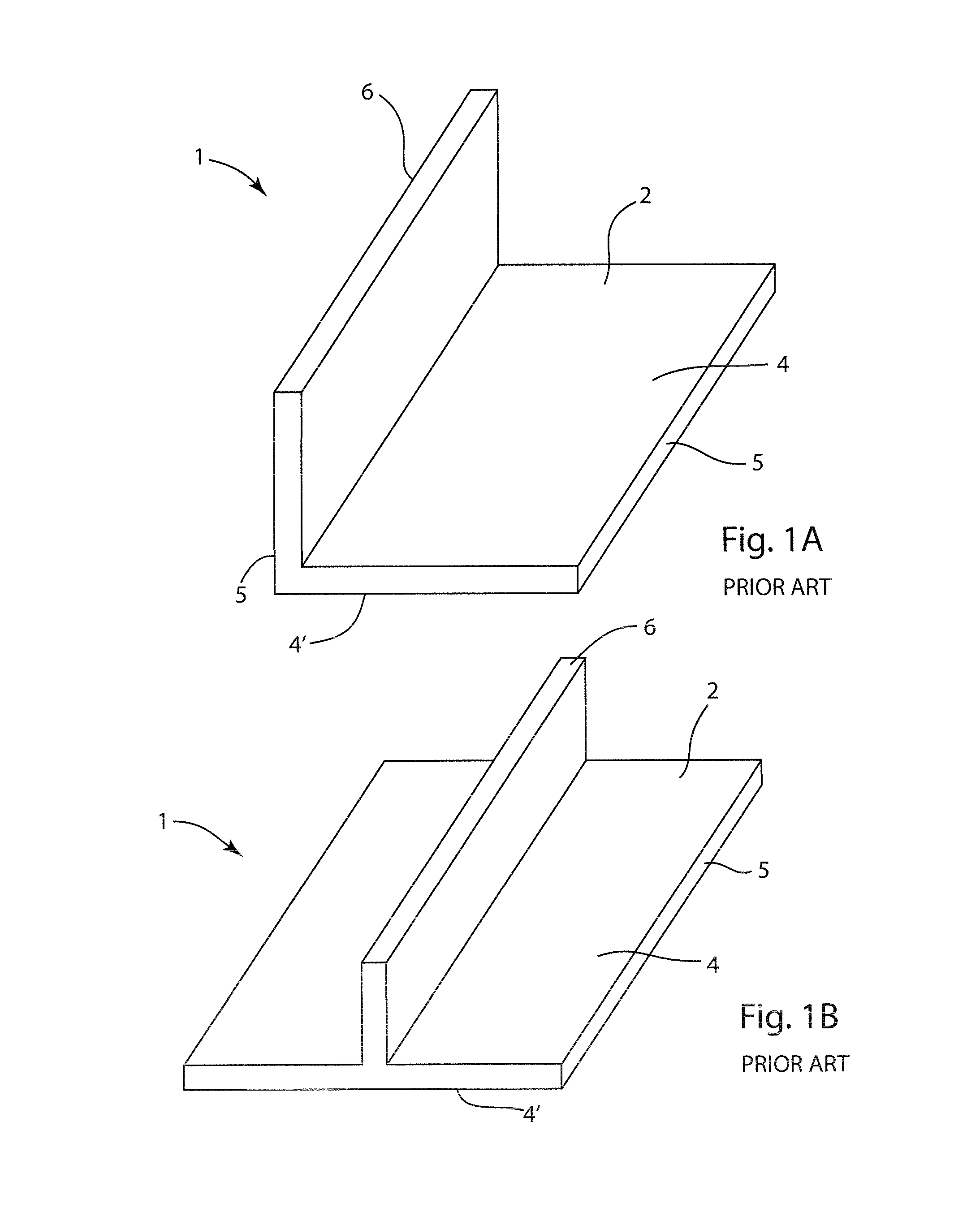
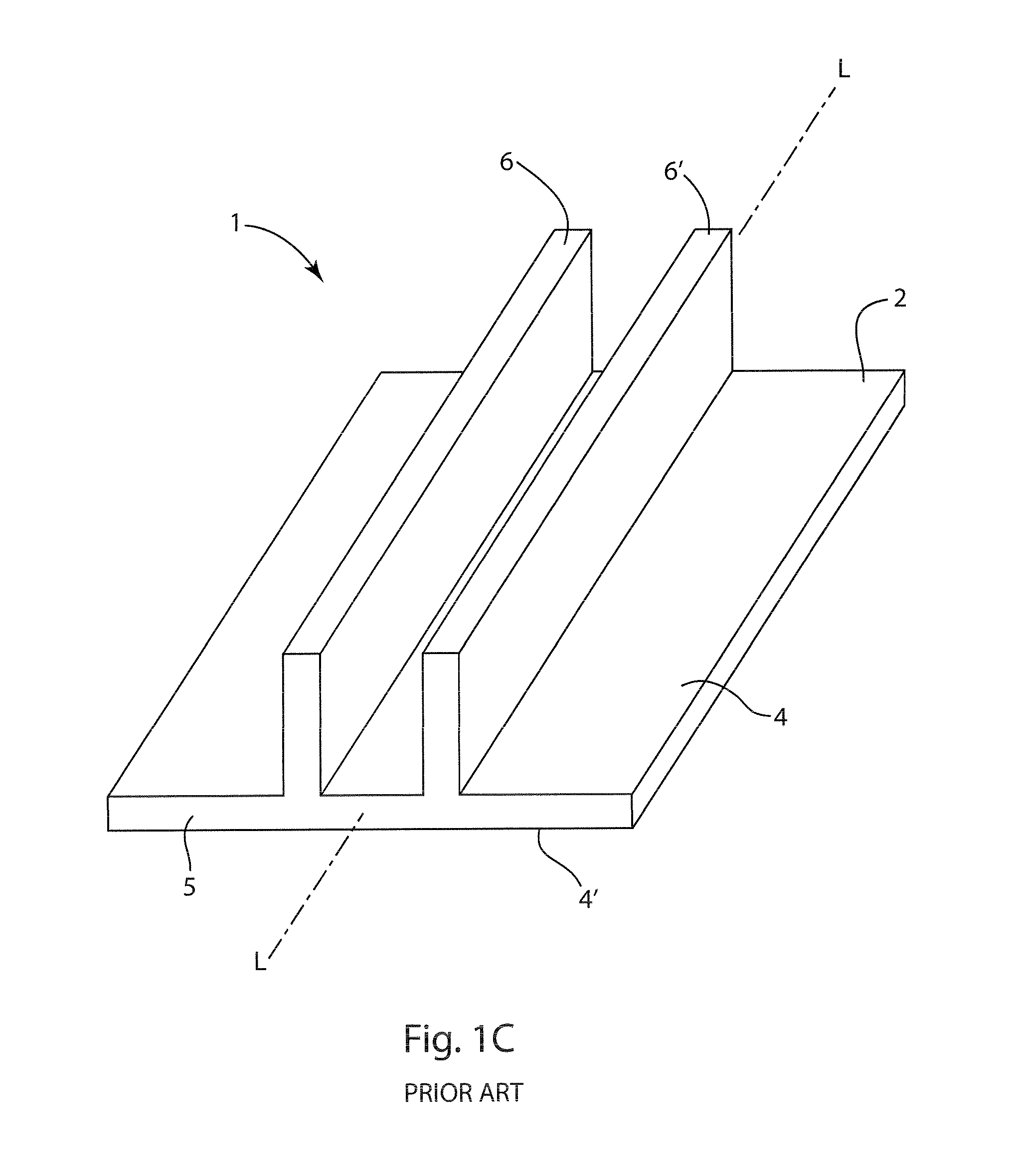
[0050]The present invention relates to three-dimensional (3D) woven preforms which can be formed into a corner fitting with lap joints without darting of the legs or flange or the addition of reinforcing materials at the corner or other locations and a method of forming such preforms. Examples of prior art 3D woven preforms 1 are shown in FIGS. 1A-1C, which illustrate L-, T-, and Pi-cross-section preforms, respectively. Other configurations of 3D preforms are possible. Planar flange 2 comprises two major surfaces 4 and 4′, at least...


PUM

PropertyMeasurementUnit
αaaaaaaaaaa
angle αaaaaaaaaaa
included angleaaaaaaaaaa

Abstract

A three-dimensional corner lap joint preform and a method of forming a three-dimensional corner lap joint preform including a woven flange with one or more legs that extend from the flange. The legs may include one or more independently woven portions which allow formation of a corner without darting the leg or adding additional reinforcement. The independently woven portions may include warp fibers which are not woven into the preform. The unwoven area allows removal of a portion of the leg prior to formation of the corner, allowing the portions of the leg to overlap and form a lap joint.

Description

INCORPORATION BY REFERENCE[0001]All patents, patent applications, documents and / or references referred to herein are incorporated by reference, and may be employed in the practice of the invention.FIELD OF THE INVENTION[0002]This invention generally relates to three-dimensional (3D) woven preforms and particularly relates to 3D woven preforms used in reinforced composite materials. More particularly, the present invention relates to preforms that can be formed into a corner fitting without darting or requiring additional reinforcing materials. More particularly still, the present invention relates to preforms that can be formed into a corner fitting with lap joints.BACKGROUND OF THE INVENTION[0003]The use of reinforced composite materials to produce structural components is now widespread, particularly in applications where their desirable characteristics of light weight, high strength, toughness, thermal resistance, and ability to be formed and shaped can be used to great advantage...

Claims


Application Information

Patent Timeline
Patent Type & Authority Patents(United States)
IPC IPC(8): D03D25/00B29B11/16D03D3/00D03D23/00
CPCB29B11/16D03D25/005D03D3/00D03D23/00D10B2101/06D10B2101/08D10B2101/12D10B2331/021D10B2331/04D10B2505/02Y10T428/24479D03D25/00
Inventor MCCLAIN, MICHAELGOERING, JONATHAN
Owner ALBANY ENGINEERED COMPOSITES
Why Eureka
Try Eureka