
Head mounted display device with wide field of view

a display device and wide field of view technology, applied in static indicating devices, optics, instruments, etc., can solve the problems of increasing design difficulty, increasing production cost, deteriorating display quality, etc., and achieve the effect of improving display quality

Active Publication Date: 2021-02-09
HTC CORP
View PDF11 Cites 0 Cited by
  • Summary
  • Abstract
  • Description
  • Claims
  • Application Information

AI Technical Summary

Benefits of technology

[0005]The invention provides a head mounted display device capable of improving the display quality.
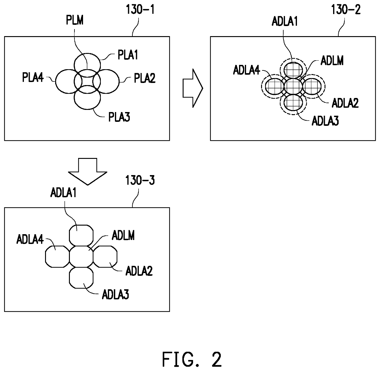
[0007]Based on the above, the invention provides the head mounted display device disposed with the micro-lens array substrate to adjust the characteristics of the projection surfaces of the pin-lights by the micro-lenses on the micro-lens array substrate so areas of the overlapping regions of the projection surfaces of the adjusted lights projected on the transparent LCD panel may be effectively reduced. In this way, the issue regarding poor brightness uniformity may be easily solved, and the display quality may also be improved without increasing the cost and the design complexity of the head mounted display device.

Problems solved by technology

However, because projection surfaces of the pin-lights would overlap with each other on the liquid crystal panel and luminances of overlapping regions would be relatively high, the display image generated by the liquid crystal panel may show of a honeycomb-like effect, thereby deteriorating the display quality.
To avoid such a phenomenon, the display image is compensated by performing complex calculations in the conventional technology, which not only increases the difficulty in design but also increases the production cost.

Method used


Image

  • Head mounted display device with wide field of view
  • Head mounted display device with wide field of view
  • Head mounted display device with wide field of view

Examples


Embodiment Construction

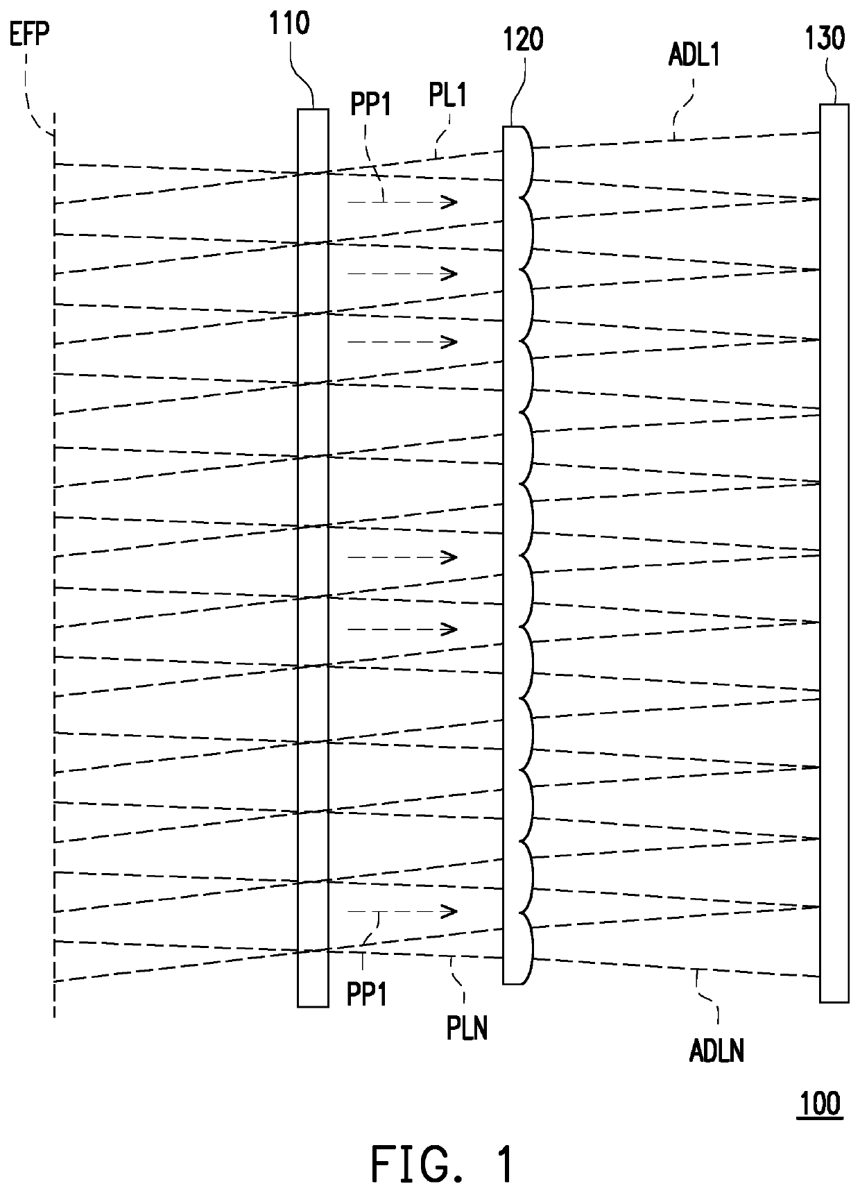
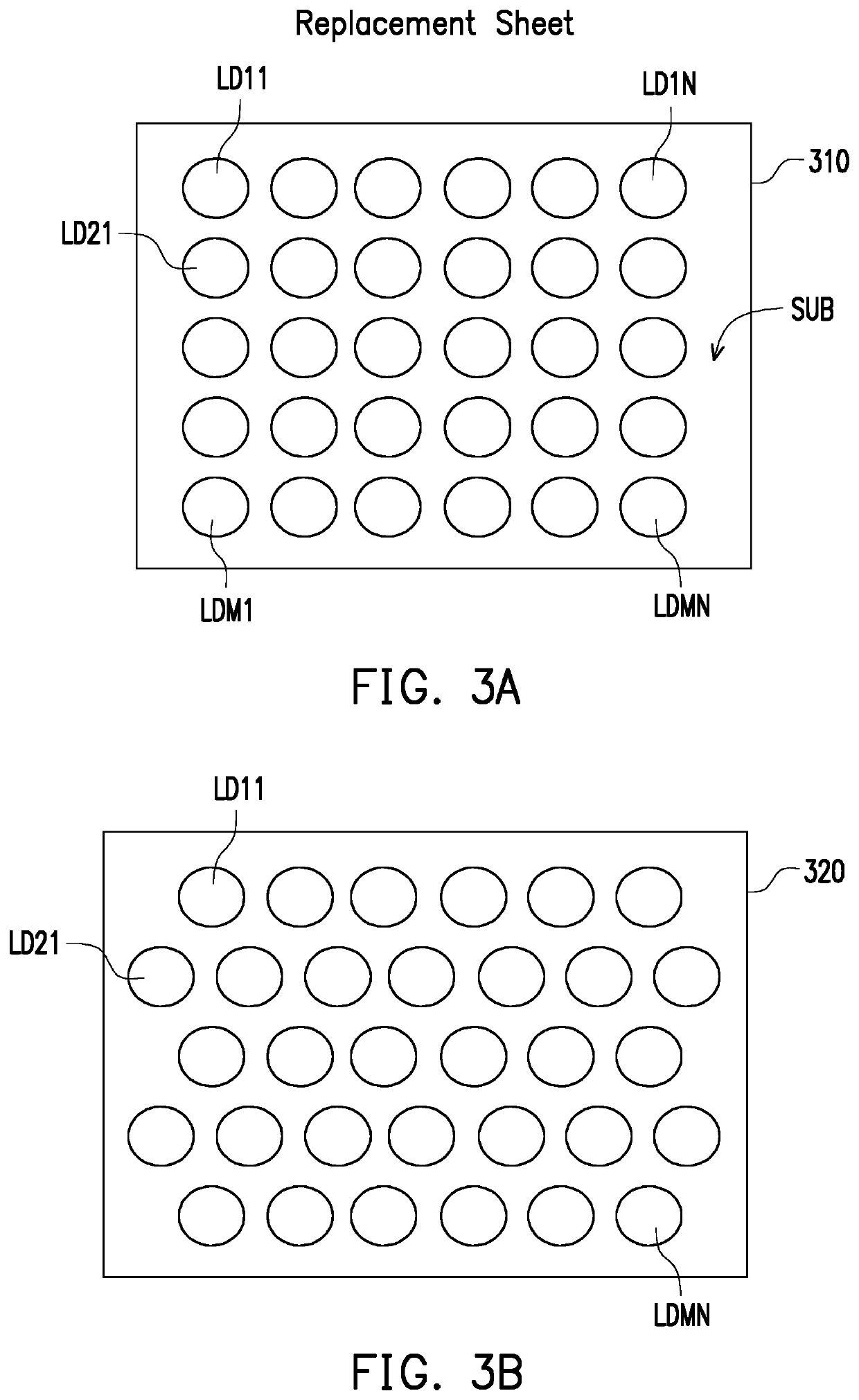
[0014]With reference to FIG. 1, FIG. 1 is a schematic diagram illustrating a head mounted display device in an embodiment of the invention. A head mounted display device 100 includes a transmissive light source 110, a micro-lens array substrate 120 and a transparent liquid crystal display (LCD) panel 130. The transmissive light source 110 is disposed with a plurality of light emitting elements, and separately emits a plurality of pin-lights PL1 to PLN to the micro-lens array substrate 120 along a light projection path PP1. The micro-lens array substrate 120 is disposed with a plurality of micro-lenses, which are used to respectively receive the pin-lights PL1 to PLN and respectively adjust characteristics of a plurality of projection surfaces of the pin-lights PL1 to PLN to generate a plurality of adjusted lights ADL1 to ADLN. The adjusted lights ADL1 to ADLN are projected to the transparent LCD panel 130.

[0015]The transparent LCD panel 130 receives the adjusted lights ADL1 to ADLN ...


PUM

PropertyMeasurementUnit
shapesaaaaaaaaaa
transparentaaaaaaaaaa
brightnessaaaaaaaaaa

Abstract

A head mounted display (HMD) includes a first transparent light source, a first micro-lens array panel and a first transparent LCD panel. The first transparent light source emits a plurality of pin-lights along a first light projection path. The first micro-lens array panel having a plurality of micro-lens, and the micro-lens respectively receive the pin-lights and adjust characteristics of projection surfaces of the pin-lights to generate a plurality of adjusted lights. The first transparent LCD panel receives the adjusted lights and generates a first display image according to the adjusted lights.

Description

CROSS-REFERENCE TO RELATED APPLICATION[0001]This application claims the priority benefit of U.S. provisional application Ser. No. 62 / 506,620, filed on May 16, 2017. The entirety of the above-mentioned patent application is hereby incorporated by reference herein and made a part of this specification.BACKGROUND OF THE INVENTIONField of the Invention[0002]The invention relates to a head mounted display device, and more particularly, to a head mounted display device with wide field of view.Description of Related Art[0003]With the advancement of electronic technology, head-mounted display devices that can provide display effects of virtual reality and augmented reality have become a new and popular display device.[0004]In a head mounted display device with wide field of view in the existing technical field, a plurality of pin-lights are disposed to form an illumination array so a display image can be generated by a liquid crystal panel through a light field image algorithm. However, bec...

Claims


Application Information

Patent Timeline
Patent Type & Authority Patents(United States)
IPC IPC(8): G02B27/01G02F1/1335G02B3/00G09G3/00G02B27/00
CPCG02B27/0172G02B3/0037G02B27/0075G09G3/00G02B2027/014G02B2027/0127G02B2027/0132G02F1/133526
Inventor FAN, FU-CHENGCHEN, CHUNG-JUNGLIN, CHUN-TA
Owner HTC CORP
Learn More