
Sealing washer for a rotor, and rotor with such a washer

a washer and rotor technology, applied in the field of sealing washers, can solve the problems of not sealing completely and remaining

Active Publication Date: 2022-06-21
SIEMENS ENERGY GLOBAL GMBH & CO KG
View PDF12 Cites 0 Cited by
  • Summary
  • Abstract
  • Description
  • Claims
  • Application Information

AI Technical Summary

Benefits of technology

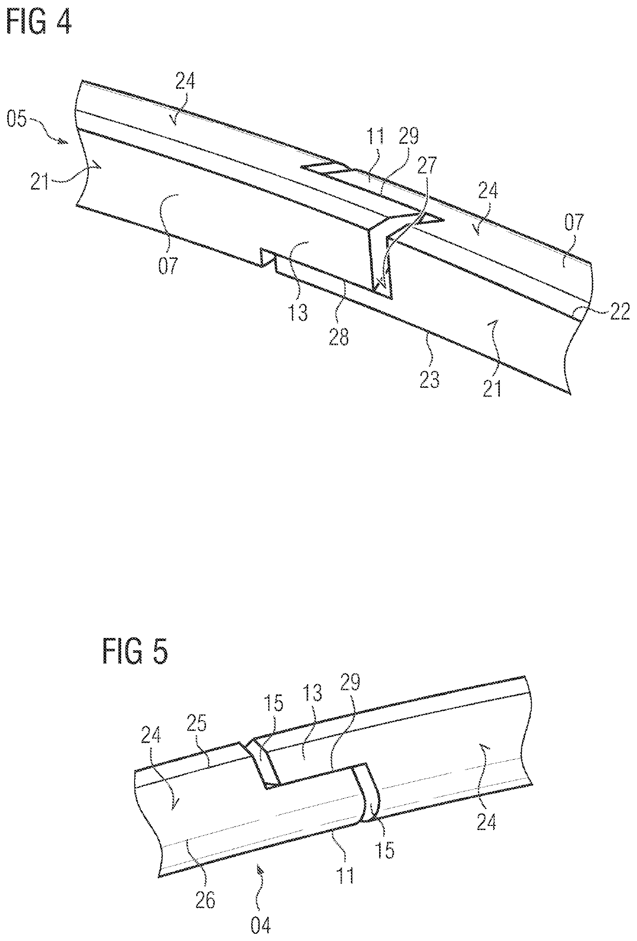
[0016]The embodiment according to the invention makes it possible for the triangular section and the pressing section as overlapping sections of the sealing washer to likewise be provided at least to some extent with a section of the supporting face, with the result that sealing can be substantially ensured even in this region. In this way, leakage in the region of the overlap can be reduced further in comparison with the embodiment in the prior art.
[0021]Regardless of the presence of two or more washer segments, it is advantageous, furthermore, if there is a closing washer segment. It is provided here that there is a triangular section on both sides on the closing washer segment. This simplifies final assembly of the closing washer segment in order to form the sealing washer.
[0024]Generally speaking, it is to be assumed that the gap to be sealed between the adjacent rotor components is small in comparison with the width of the sealing washer. Accordingly, for sealing purposes, the spacing of the supporting face and therefore the outer bearing edge from the bearing face and therefore from the outer bearing edge is advantageously selected to be not greater than 0.2 times the sealing washer width, as measured in the axial direction. In this way, sealing can take place with optimum closeness to the gap.
[0026]In order to avoid a sharp-edged groove in a rotor disk for the arrangement of the sealing washer with consideration of an installation space which is as small as possible for the sealing washer and in the process ensuring the necessary stability of the sealing washer, it is advantageous if said sealing washer is rounded in a manner which lies opposite the bearing face. To this extent, as viewed in cross section, the sealing washer has an arcuate section opposite the bearing face adjacently with respect to the supporting face in a manner which points radially inward. This makes an analogous shape in the rotor disk possible and therefore avoids the formation of stress peaks in the circumferential groove which is required to this end (and is continuous in the circumferential direction or is in multiple pieces).
[0027]To this end, it is advantageous, furthermore, if a straight section is arranged opposite the supporting face on the side which faces the rotor axis, which straight section connects the arcuate section directly or indirectly to the bearing face or the inner bearing edge.
[0030]It is then provided according to the invention to use an improved solution of the sealing washer as described above, and therefore to further improve the sealing.

Problems solved by technology

It is disadvantageous in the case of the known embodiment, however, that a gap, which, even if it is very small, is not sealed completely, remains in the case of the overlap.

Method used


Image

  • Sealing washer for a rotor, and rotor with such a washer
  • Sealing washer for a rotor, and rotor with such a washer
  • Sealing washer for a rotor, and rotor with such a washer

Examples


Embodiment Construction

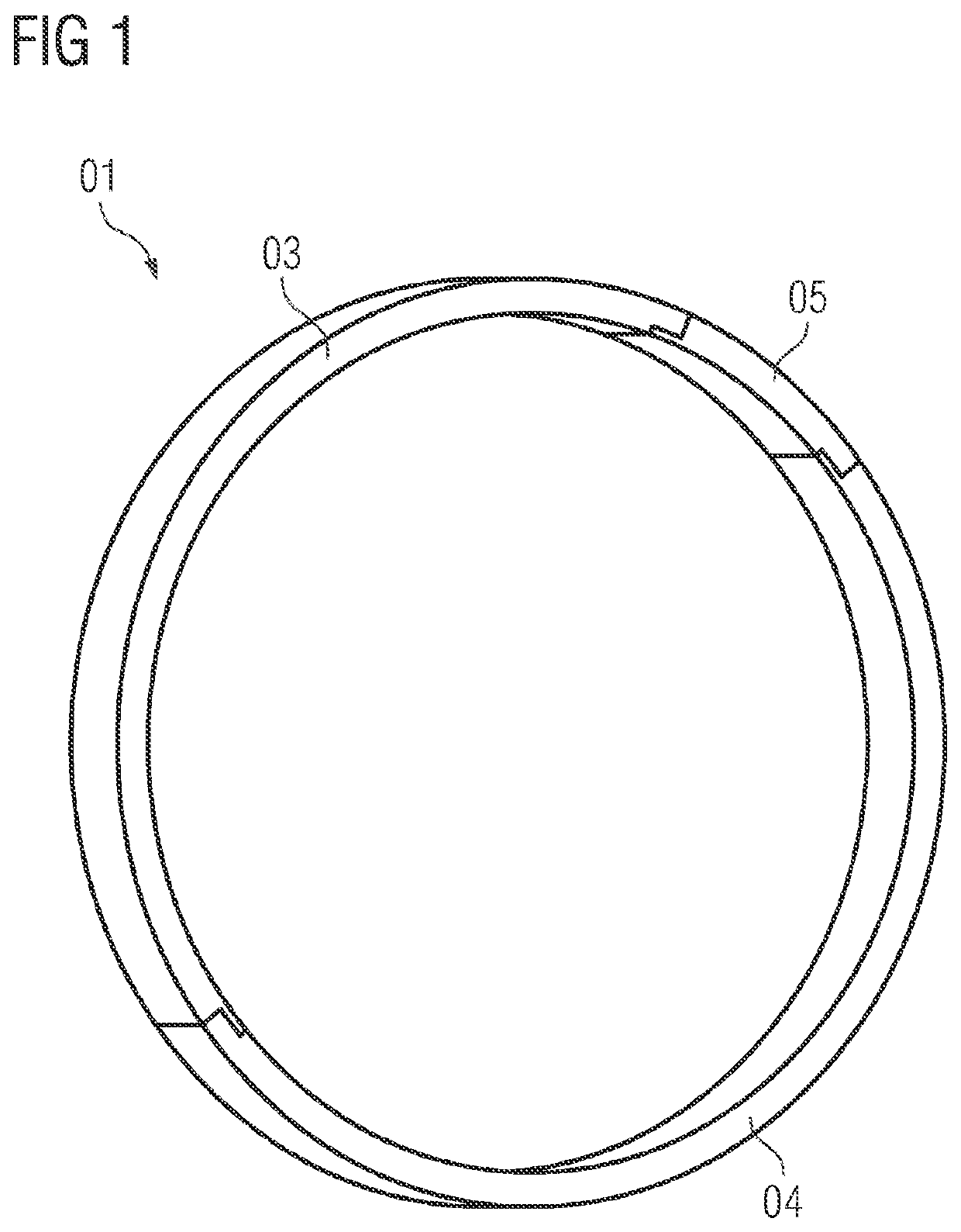
[0043]FIG. 1 shows a perspective view of one exemplary embodiment of a sealing washer 01. In said exemplary embodiment, the sealing washer 01 consists of three washer segments 03, 04, 05, two washer segments 03 and 04 being configured as identical parts and extending over an angle of a little more than 170°. Furthermore, there is a closing washer segment 05 which 05 extends over an angular range of approximately 15°; see also FIG. 7.

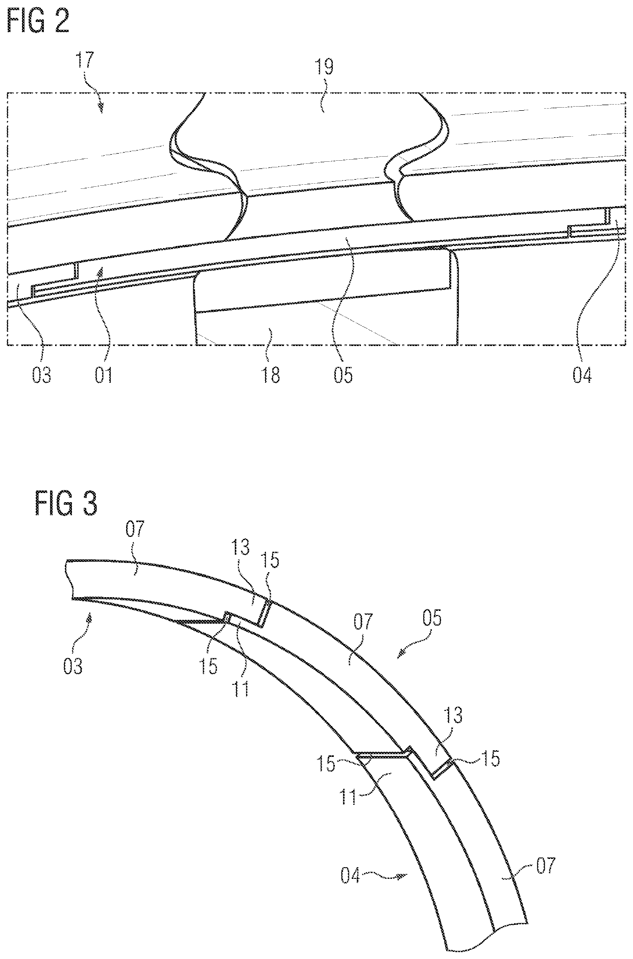
[0044]As can be seen to some extent from FIG. 2, the sealing washer 01 is received in a groove on a rotor disk 17. Here, said rotor disk 17 has a plurality of blade holding grooves 18 in a manner which is distributed over the circumference, in which blade holding grooves 18 rotor blades 19 are in each case fastened by way of a blade root. The closing washer segment 05 is arranged in front of a blade holding groove 18 and therefore in front of the blade root of the rotor blade 19. The overlapping region which is present on both sides with respect to the a...


PUM


Abstract

A sealing washer for use in a rotor of a gas turbine, sealing being brought about on one side of the sealing washer by an approximately radially oriented bearing face and on the other side by way of a supporting face which is oriented in an inclined manner with respect to the rotor axis. The sealing washer is of split configuration and has at least one washer segment with a circumferential washer section. At the dividing point, a pressing section and a triangular section overlap along a dividing face. Here, the dividing face intersects the bearing face and makes sealing both with the pressing section and with the triangular section possible. In order to also make sealing on the supporting face with the pressing section and the triangular section possible, the triangular section is reduced to at most 0.3 times the cross-sectional area of the washer section.

Description

CROSS REFERENCE TO RELATED APPLICATIONS[0001]This application claims the benefit of European Application No. EP20165112 filed 24 Mar. 2020, incorporated by reference herein in its entirety.FIELD OF INVENTION[0002]The invention relates to a two-piece or multiple-piece sealing washer for use in a rotor, in particular in a gas turbine, the ends of the sealing washer overlapping, in order in this way to reduce leakage through the gap which is formed. It is provided here that the sealing washer brings about sealing with respect to further rotor components by means of the centrifugal force. In the case of the present type here, the cross section of the sealing washer is very small in comparison with its diameter.BACKGROUND OF INVENTION[0003]The prior art has disclosed a sealing washer which has two sealing faces which are arranged at an angle with respect to one another and, in the case of rotation of the rotor, bring about sealing of a gap by means of the centrifugal force. Here, one of ...

Claims


Application Information

Patent Timeline
Patent Type & Authority Patents(United States)
IPC IPC(8): F01D5/30
CPCF01D5/30F05D2220/32F05D2240/30F05D2240/55F16J15/3268F16J15/3284F01D5/3007F01D5/3015F05D2250/182F05D2260/36F05D2250/11F05D2250/13F01D11/006F01D11/003F01D5/02
Inventor KRÜTZFELDT, JOACHIMSCHRÖDER, PETER
Owner SIEMENS ENERGY GLOBAL GMBH & CO KG
Learn More