[0008]As previously mentioned, the best characteristic of class AB and G amplifiers is their fast and quiet operation. In contrast, class D amplifiers are efficient but slow, and produce a noisy output. In a typical prior art series-hybrid-linear amplifier, the power supply voltages are expected to remain as close in value to the output as possible. Therefore, a class D switching amplifier is typically configured to drive the supply rails of the linear stage, which forces the supply rails to closely track the output signal (output voltage), which prevents excessive power consumption in the linear stage. In essence, the linear stage is positioned at the output of the class D amplifier, absorbing the ripple (noise) appearing on the output. However, most present day amplifiers that attempt to combine the best features of both topologies—i.e. low-noise, high-speed, and high-efficiency—are complex and only partially successful at achieving the desired speed, efficiency, and noise-free operation.
[0009]Various embodiments of an amplifier architecture disclosed herein achieve low-noise, high-speed, and high-efficiency operation without requiring excessive complexity. Prior art solutions typically combine linear amplifiers (Class AB or G) and switching amplifiers (Class D) in a series or parallel arrangement in which the linear stage delivers high current at low voltage, or high voltage at low current, but not high current and high voltage at the same time. In such arrangements, the switching amplifier delivers the bulk of the output power.
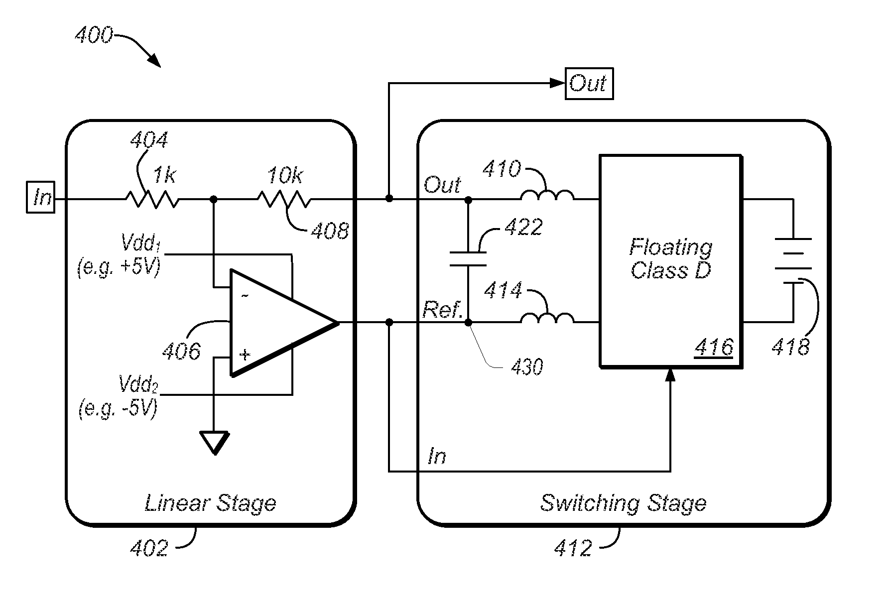
[0010]The various embodiments of the amplifier architecture disclosed herein differ from prior art amplifiers in at least two key areas. First, a switching amplifier is electrically isolated from a linear amplifier, and the output of the linear amplifier is used to provide the signal reference to the floating switching amplifier, instead of the signal reference of the switching amplifier being provided by an actual reference (e.g. ground). This simplifies coupling the two amplifiers in series, and obviates the need to provide a high-voltage power supply to the linear amplifier. As a result of the electrical isolation the linear amplifier does not require a high-voltage power supply. In one set of embodiments, the electrical isolation may be achieved by independently powering the two amplifiers. Second, rather than the linear amplifier stage delivering the full load-current—which is typically the case for series-configured hybrid amplifiers—the output of the linear amplifier may be high-pass filtered, allowing the (majority of the steady-state) output current to flow through an inductor almost without loss from ground. More specifically, the high-pass filter may include an inductor coupled across the output of the linear amplifier stage and an actual signal / voltage reference (e.g. ground), allowing the output current to flow through the inductor. These two structural improvements result in a circuit that is relatively simple while delivering the promised benefits of a hybrid switching / linear power amplifier.
[0011]Typically, a switching amplifier imposes a certain voltage between two nodes at its output, where one of the two nodes is the output node, and the other node is generally ground, also referred to herein as “actual ground”. Accordingly the output voltage is the potential difference between the output node and ground. In various embodiments, the output generated by a floating switching stage in a hybrid amplifier may be referenced to and regulated with respect to a reference that may be adjusted using a linear stage in the hybrid amplifier, to maintain an output with substantially reduced noise (or a noise-free output) with respect to ground. In this manner, any noise (also referred to herein as ripples and / or transients) that may be present in the output signal (provided by the switching stage) may be counteracted by the linear stage driving the reference node. In other words, the output may be referenced to the output of the linear stage, which may move the value of the reference, and therefore the value of the output signal, according to noise / transients generated on the output signal, to counteract and eliminate the noise on the output signal. The amplitude (or voltage value) of the output signal provided the hybrid amplifier, for example to a load, is still with respect to actual ground, but by allowing the switching stage to float with respect to actual ground, noise on the output of the hybrid amplifier may be counteracted in an efficient manner. This may be accomplished by sensing the output of the switching stage through a feedback loop to the input of the linear stage, which therefore allows compensating for the noise on the output of the switching stage.
[0012]In various embodiments, an amplifier structure may include a switching amplifier that generates a first amplified output signal having an amplitude with respect to a reference value at a reference node, and may further include a linear amplifier coupled to the switching amplifier and generating a second amplified output signal. The linear amplifier may adjust the reference value at the reference node, for example by driving the reference node with the second amplified output signal, to counteract transients and / or noise generated on the first amplified output signal. The switching amplifier may drive a load with the first amplified output signal, and may adjust the amplitude of the first amplified output signal according to at least the second amplified output signal. Specifically, the switching amplifier may increase the amplitude of the first amplified output signal when the second amplified output signal has a positive amplitude with respect to actual ground, and / or it may decrease the amplitude of the first amplified output signal when the second amplified output signal has a negative amplitude with respect to actual ground.
[0014]In some embodiments, a hybrid amplifier may be designed to have an input terminal that receives an input signal, and an output terminal that provides an output signal having an amplitude with respect to a reference voltage. The hybrid amplifier may include a linear amplifier stage that generates an intermediate amplified signal based on the input signal, and adjusts the reference voltage responsive to transient changes in the output signal. A resistive feedback path provided from the output terminal to the input of the linear amplifier may enable the linear amplifier stage to sense the transient changes in the output signal. A switching amplifier stage coupled to the linear stage may generate the output signal based on the intermediate amplified signal, and provide the output signal at the output terminal. The reference voltage may be provided at a reference node, and the linear amplifier stage may adjust the reference voltage by driving the reference node with the intermediate amplified output signal. The hybrid amplifier may be operated to drive a load with the output signal, and may increase the amplitude of the output signal when the intermediate amplified signal has a positive amplitude with respect to actual ground, and decrease the amplitude of the output signal when the intermediate amplified signal has a negative amplitude with respect to actual ground.


