Efficient Low Noise High Speed Amplifier

a high-speed amplifier and low-noise technology, applied in the direction of low-noise amplifiers, low-frequency amplifiers, rf amplifiers, etc., can solve the problems of high-efficiency, high-efficiency, day amplifiers that try to combine the best features, etc., to prevent excessive power consumption in the linear stage, reduce noise, and improve efficiency

Active Publication Date: 2015-06-18
NATIONAL INSTRUMENTS
View PDF5 Cites 13 Cited by
  • Summary
  • Abstract
  • Description
  • Claims
  • Application Information

AI Technical Summary

Benefits of technology

[0008]As previously mentioned, the best characteristic of class AB and G amplifiers is their fast and quiet operation. In contrast, class D amplifiers are efficient but slow, and produce a noisy output. In a typical prior art series-hybrid-linear amplifier, the power supply voltages are expected to remain as close in value to the output as possible. Therefore, a class D switching amplifier is typically configured to drive the supply rails of the linear stage, which forces the supply rails to closely track the output signal (output voltage), which prevents excessive power consumption in the linear stage. In essence, the linear stage is positioned at the output of the class D amplifier, absorbing the ripple (noise) appearing on the output. However, most present day amplifiers that attempt to combine the best features of both topologies—i.e. low-noise, high-speed, and high-efficiency—are complex and only partially successful at achieving the desired speed, efficiency, and noise-free operation.
[0009]Various embodiments of an amplifier architecture disclosed herein achieve low-noise, high-speed, and high-efficiency operation without requiring excessive complexity. Prior art solutions typically combine linear amplifiers (Class AB or G) and switching amplifiers (Class D) in a series or parallel arrangement in which the linear stage delivers high current at low voltage, or high voltage at low current, but not high current and high voltage at the same time. In such arrangements, the switching amplifier delivers the bulk of the output power.
[0010]The various embodiments of the amplifier architecture disclosed herein differ from prior art amplifiers in at least two key areas. First, a switching amplifier is electrically isolated from a linear amplifier, and the output of the linear amplifier is used to provide the signal reference to the floating switching amplifier, instead of the signal reference of the switching amplifier being provided by an actual reference (e.g. ground). This simplifies coupling the two amplifiers in series, and obviates the need to provide a high-voltage power supply to the linear amplifier. As a result of the electrical isolation the linear amplifier does not require a high-voltage power supply. In one set of embodiments, the electrical isolation may be achieved by independently powering the two amplifiers. Second, rather than the linear amplifier stage delivering the full load-current—which is typically the case for series-configured hybrid amplifiers—the output of the linear amplifier may be high-pass filtered, allowing the (majority of the steady-state) output current to flow through an inductor almost without loss from ground. More specifically, the high-pass filter may include an inductor coupled across the output of the linear amplifier stage and an actual signal / voltage reference (e.g. ground), allowing the output current to flow through the inductor. These two structural improvements result in a circuit that is relatively simple while delivering the promised benefits of a hybrid switching / linear power amplifier.
[0011]Typically, a switching amplifier imposes a certain voltage between two nodes at its output, where one of the two nodes is the output node, and the other node is generally ground, also referred to herein as “actual ground”. Accordingly the output voltage is the potential difference between the output node and ground. In various embodiments, the output generated by a floating switching stage in a hybrid amplifier may be referenced to and regulated with respect to a reference that may be adjusted using a linear stage in the hybrid amplifier, to maintain an output with substantially reduced noise (or a noise-free output) with respect to ground. In this manner, any noise (also referred to herein as ripples and / or transients) that may be present in the output signal (provided by the switching stage) may be counteracted by the linear stage driving the reference node. In other words, the output may be referenced to the output of the linear stage, which may move the value of the reference, and therefore the value of the output signal, according to noise / transients generated on the output signal, to counteract and eliminate the noise on the output signal. The amplitude (or voltage value) of the output signal provided the hybrid amplifier, for example to a load, is still with respect to actual ground, but by allowing the switching stage to float with respect to actual ground, noise on the output of the hybrid amplifier may be counteracted in an efficient manner. This may be accomplished by sensing the output of the switching stage through a feedback loop to the input of the linear stage, which therefore allows compensating for the noise on the output of the switching stage.
[0012]In various embodiments, an amplifier structure may include a switching amplifier that generates a first amplified output signal having an amplitude with respect to a reference value at a reference node, and may further include a linear amplifier coupled to the switching amplifier and generating a second amplified output signal. The linear amplifier may adjust the reference value at the reference node, for example by driving the reference node with the second amplified output signal, to counteract transients and / or noise generated on the first amplified output signal. The switching amplifier may drive a load with the first amplified output signal, and may adjust the amplitude of the first amplified output signal according to at least the second amplified output signal. Specifically, the switching amplifier may increase the amplitude of the first amplified output signal when the second amplified output signal has a positive amplitude with respect to actual ground, and / or it may decrease the amplitude of the first amplified output signal when the second amplified output signal has a negative amplitude with respect to actual ground.
[0014]In some embodiments, a hybrid amplifier may be designed to have an input terminal that receives an input signal, and an output terminal that provides an output signal having an amplitude with respect to a reference voltage. The hybrid amplifier may include a linear amplifier stage that generates an intermediate amplified signal based on the input signal, and adjusts the reference voltage responsive to transient changes in the output signal. A resistive feedback path provided from the output terminal to the input of the linear amplifier may enable the linear amplifier stage to sense the transient changes in the output signal. A switching amplifier stage coupled to the linear stage may generate the output signal based on the intermediate amplified signal, and provide the output signal at the output terminal. The reference voltage may be provided at a reference node, and the linear amplifier stage may adjust the reference voltage by driving the reference node with the intermediate amplified output signal. The hybrid amplifier may be operated to drive a load with the output signal, and may increase the amplitude of the output signal when the intermediate amplified signal has a positive amplitude with respect to actual ground, and decrease the amplitude of the output signal when the intermediate amplified signal has a negative amplitude with respect to actual ground.

Problems solved by technology

In contrast, class D amplifiers are efficient but slow, and produce a noisy output.
However, most present day amplifiers that attempt to combine the best features of both topologies—i.e. low-noise, high-speed, and high-efficiency—are complex and only partially successful at achieving the desired speed, efficiency, and noise-free operation.

Method used


Image

  • Efficient Low Noise High Speed Amplifier
  • Efficient Low Noise High Speed Amplifier
  • Efficient Low Noise High Speed Amplifier

Examples


first embodiment

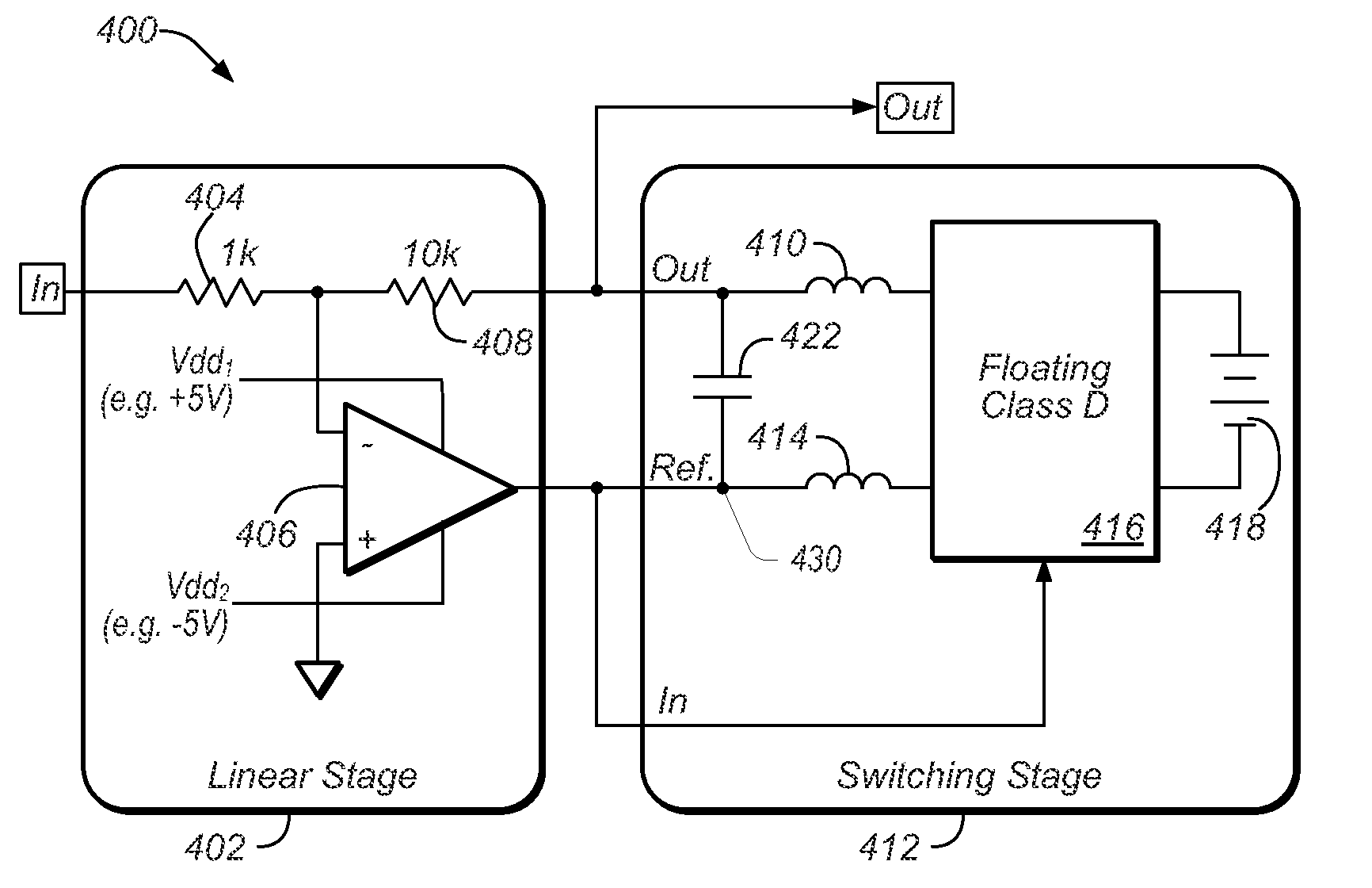
[0032]FIG. 4 shows a simplified circuit diagram of an efficient, low-noise, and high-power hybrid amplifier 400, which may provide an output voltage “Out”, for example to a load (not shown). A linear (amplifier) stage 402 is series coupled to a switching (amplifier) stage 412. The output of switching stage 412 is provided by a class D amplifier component 416, which is powered by a floating supply 418. The output (Out) is referenced to a reference node 430 at one end of output capacitor 422, which is coupled to inductors 410 and 414 as shown. Because switching stage 412 is regulating its output voltage with respect to Ref node 430 as opposed to regulating its output with respect to actual (signal) ground, the output is in effect referenced to the output of the linear stage 402 provided by the output of operational amplifier 406. Thus, the linear stage 402 may be operated to adjust the reference voltage at node 430 according to noise generated on the output of switching stage 412 to c...

second embodiment

[0036]FIG. 5 shows a simplified circuit diagram of an efficient, low-noise, high-power hybrid amplifier 500. As seen in FIG. 5, hybrid amplifier 500 is similar to hybrid amplifier 400, with the exception of slightly modified switching stage 512. Specifically, a high-pass filter including capacitor 510 and inductor 520 may be coupled to the output of linear stage 402, the reference node 430, and actual (signal) ground 520 as shown. By including a high-pass filter, which may be an RLC filter with capacitor 510 and inductor 520 as shown, and a stabilizing resistance provided by a resistance of the output stage of operational amplifier 406), the output current may now be provided directly from the actual voltage reference (ground). Thus, the linear stage 402 may be providing the output current during transients, while in steady-state it may generate a small voltage across the inductor 520, which, in some embodiments, may result in providing a few mA of current in the inductor 520. In co...


PUM


Abstract

A hybrid amplifier includes a linear amplifier coupled in series with a switching amplifier. The linear amplifier may generate an intermediate amplified signal according to an input signal. The switching amplifier may generate an output signal according to the intermediate amplified signal, the output signal having an amplitude with respect to a reference voltage provided at a reference node. The linear amplifier may drive the reference node to adjust the reference voltage responsive to transient changes in the output signal. A high-pass filter coupled to the linear amplifier and the switching amplifier may enable the switching amplifier to provide most of the steady-state current, which may drive a load, from actual ground. The linear amplifier and switching amplifier may be independently powered, for example from a power supply having a primary winding and two electrically isolated secondary windings that respectively provide power to the linear amplifier and the switching amplifier.

Description

BACKGROUND OF THE INVENTION[0001]1. Field of the Invention[0002]This invention relates generally to the design of amplifiers and, more particularly, to the design of efficient, low-noise, high-speed amplifiers.[0003]2. Description of the Related Art[0004]Electronic amplifiers are used for increasing the power and / or amplitude of various specified signals. Most amplifiers operate by sinking current from a power supply, and controlling the output signal to match the shape of the input signal, but having a higher amplitude. Amplifiers are typically specified according to their input and output characteristics. One of the main characteristics of an amplifier is its gain, which relates the magnitude of the output signal to the magnitude of the input signal. The gain may be specified as the ratio of the output voltage and the input voltage, or the ratio of the output power and the input power. The gain relationship is oftentimes expressed as the transfer function of the amplifier. In most...

Claims


Application Information

Patent Timeline
Patent Type & Authority Applications(United States)
IPC IPC(8): H03F1/02H03F3/21H03F3/217H03F3/193
CPCH03F1/0205H03F3/193H03F3/211H03F2203/21103H03F2200/451H03F2200/294H03F3/2171H03F1/26H03F3/187H03F3/2173H03F2200/261H03F2200/432
Inventor REGIER, CHRISTOPHER G.
Owner NATIONAL INSTRUMENTS
Why Eureka
Try Eureka