Vibration control technology and interface for computer printers and scanners

a computer printer and scanner technology, applied in the field of vibration suppression in computer printers and scanners, to achieve the effect of increasing the “speed” of the machine, reducing the settle time, and increasing the acceleration

Inactive Publication Date: 2010-09-07
CONVOLVE
View PDF6 Cites 5 Cited by
  • Summary
  • Abstract
  • Description
  • Claims
  • Application Information

AI Technical Summary

Benefits of technology

[0017]It is further recognized that increasing the “speed” of a machine such as the print head or paper advance mechanism, actually means that any combination of the following is achieved: the velocity is increased, the acceleration is increased, the settle time is decreased, and / or the overall productivity is improved.

Problems solved by technology

The unwanted vibrations may be either vibrations of the structural components of the printer (or scanner); vibrations of the drive train that moves the print head; vibrations of the suspension holding the printer mechanism in its case; or vibrations of the entire printer on flexible mounts or feet.

Method used


Image

  • Vibration control technology and interface for computer printers and scanners
  • Vibration control technology and interface for computer printers and scanners
  • Vibration control technology and interface for computer printers and scanners

Examples


Embodiment Construction

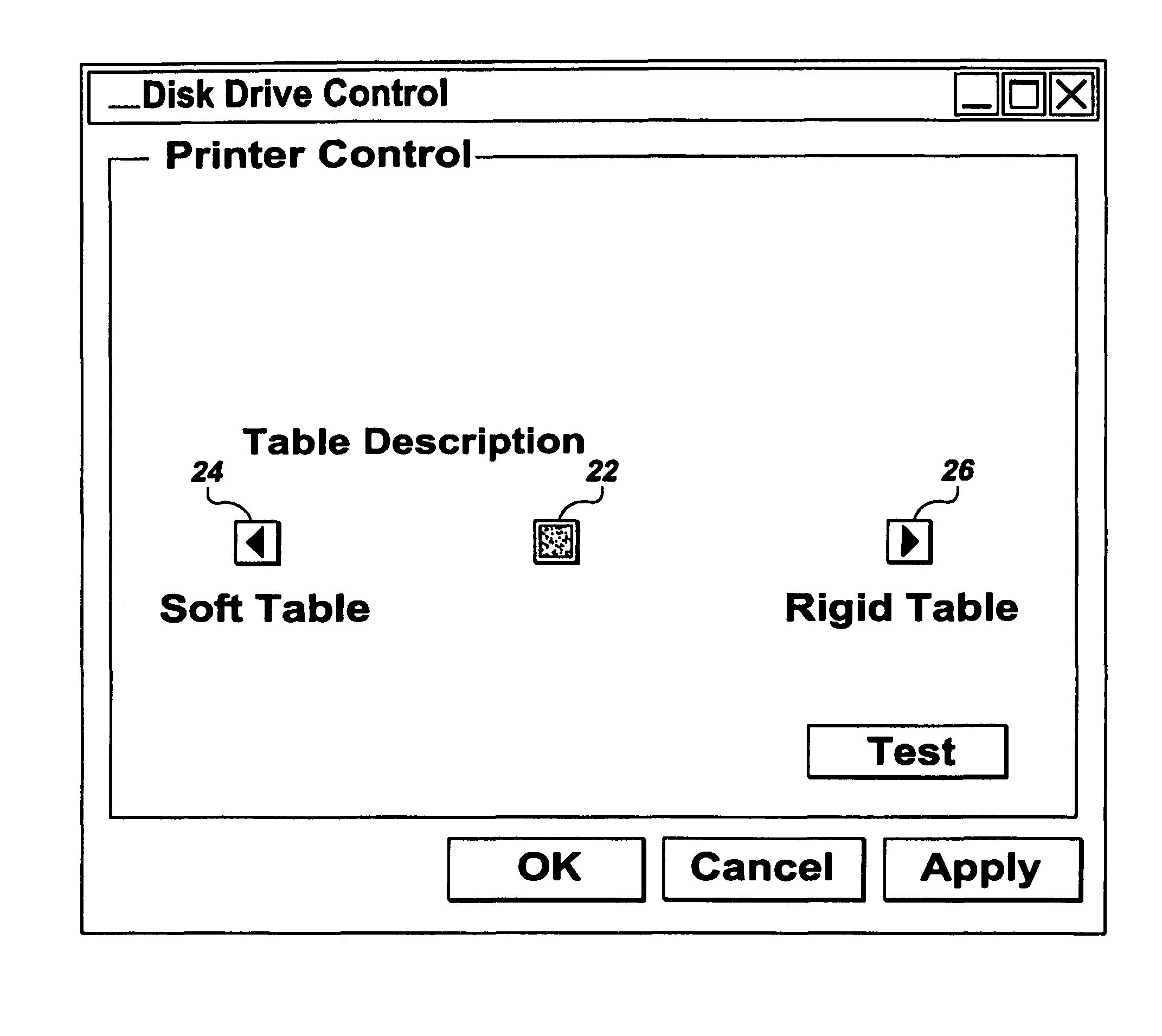
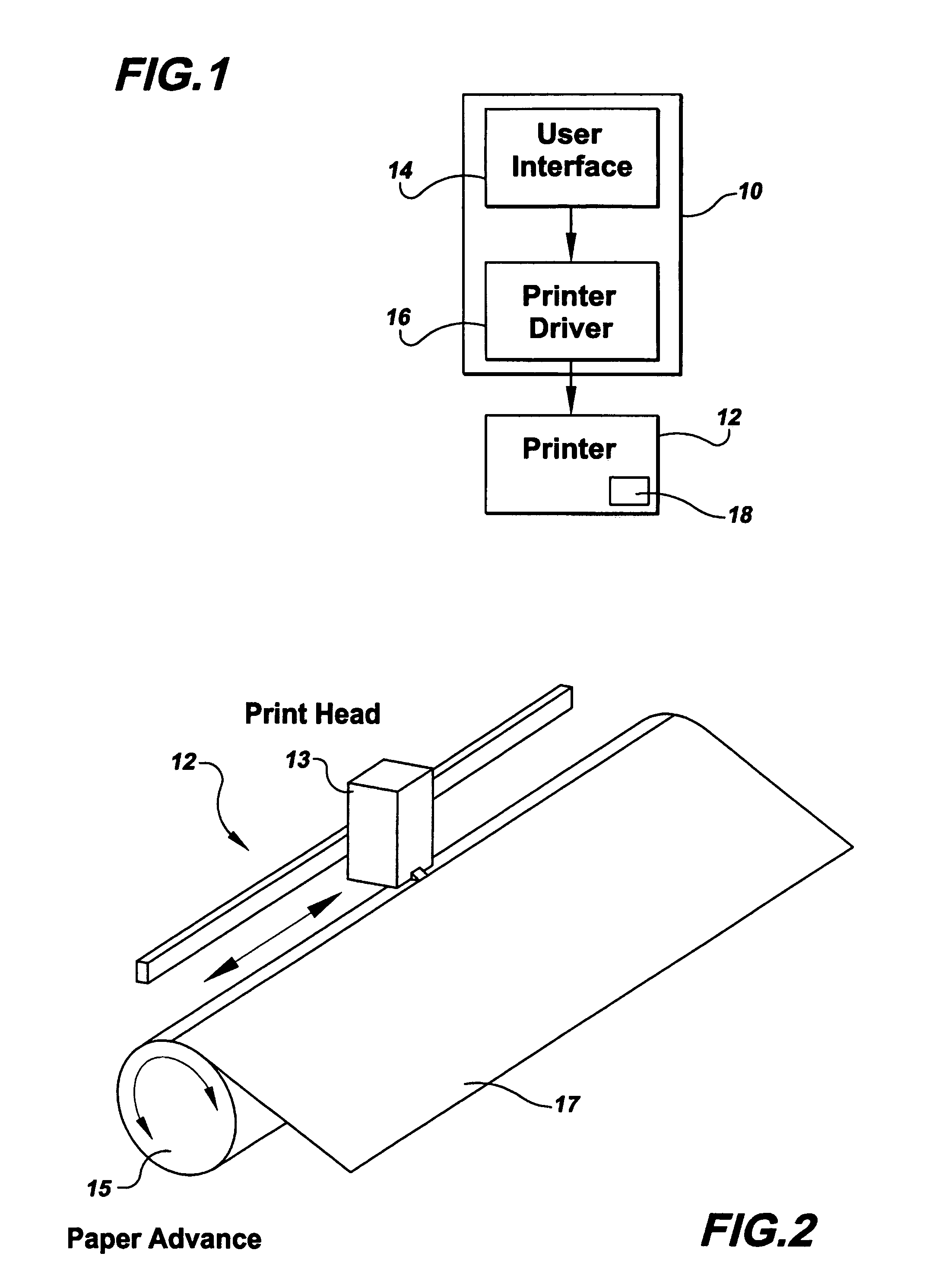
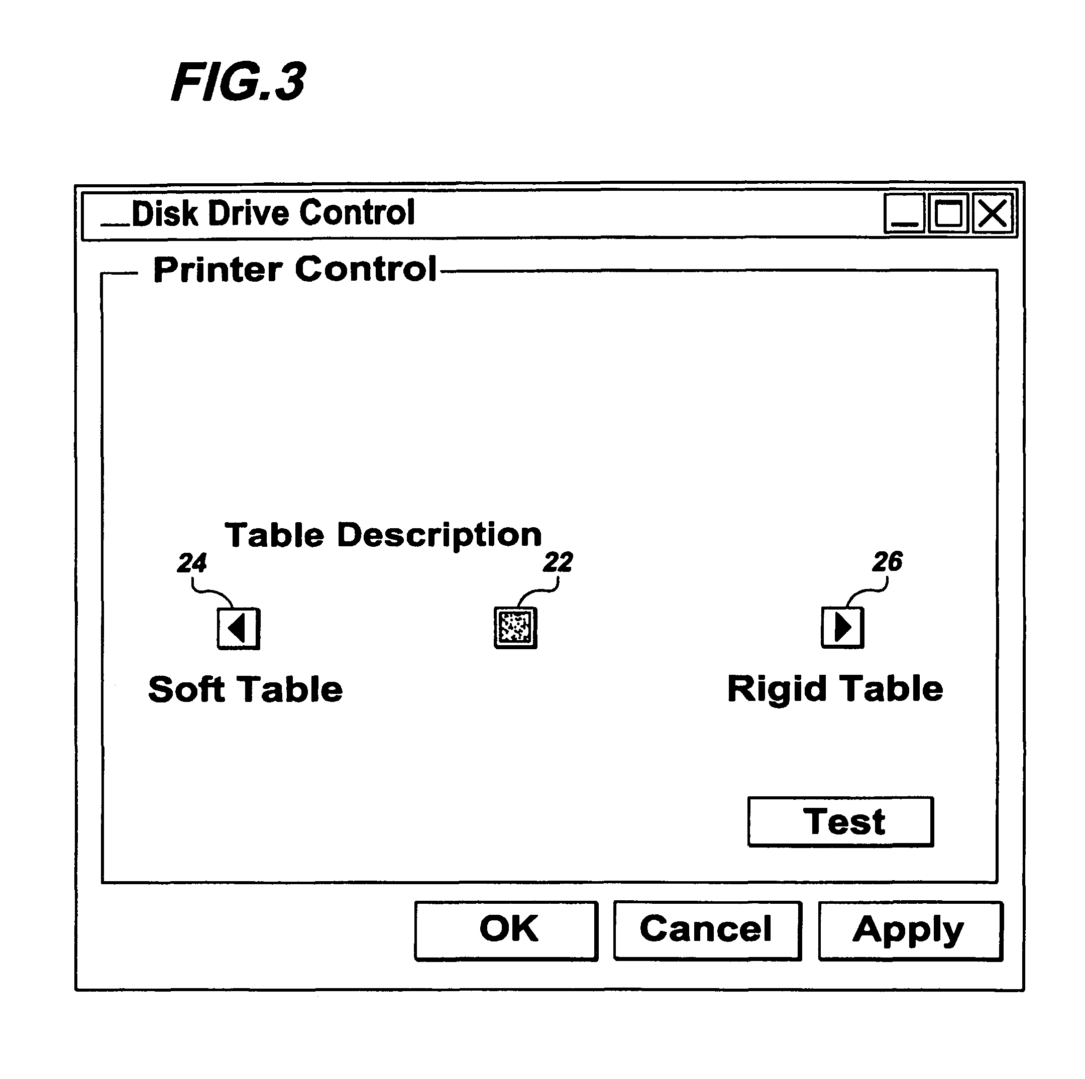
[0021]The exemplary description provided below is in terms of a printer. It is fully recognized that the same description would apply to scanners or any other computerized reproduction device that works in a similar fashion. FIG. 1 shows a block diagram of a computer 10 and printer 12. The user specifies information about the mode of operation of the printer 12 (i.e. “Quick” or “Quiet”). The user does this through a command or user interface 14. The interface 14 could be built into a printer driver 16 and appear on a print dialog box. Alternatively, the interface 14 could be a stand-alone configuration program that the user uses to periodically (or even once) change the printer's mode of operation. Alternatively, the interface 14 could be part of the printer 12 installation program.

[0022]With reference to FIG. 2, the printer 12 includes a print head 13 that is mounted for lateral translation. The printer 12 also includes a paper feed mechanism 15 that advances paper 17.

[0023]Once a ...


PUM


Abstract

Method and apparatus for altering the operation of printers and scanners to reduce vibration and/or acoustics. The technology involves altering the mode of operation of the printer or scanner to be in either “quick”, “quiet” or an intermediate mode. Additionally, structure for achieving the different modes of operation are also disclosed.

Description

[0001]This application claims priority to provisional patent application Ser. No. 60 / 201,184 filed May 2, 2000 for Vibration Control Technology and Interface for Computer Printers and Scanners.BACKGROUND OF THE INVENTION[0002]This invention relates to computer printers and scanners and, more particularly, to vibration suppression in computer printers and scanners.[0003]Vibration suppression technology developed by the inventor herein has been described in his U.S. Pat. Nos. 4,916,635 and 5,638,267 and in pending patent application Ser. No. 09 / 262,781 filed Mar. 4, 1999. The teachings of these patents and patent application are incorporated herein by reference. The technology disclosed in these references is referred to by the registered trademark Input Shaping®. As disclosed in these references, commands to a physical system are processed based on knowledge of system parameters such as vibrational frequencies, damping ratios, or measured system response, and system limitations. In p...

Claims


Application Information

Patent Timeline
Patent Type & Authority Patents(United States)
IPC IPC(8): G06K15/10G06F15/02H04N1/60B41J19/20B41J29/08H04N1/00H04N1/23
CPCB41J19/202H04N1/00795H04N1/00811H04N1/00822H04N1/2307H04N1/2338H04N1/2369B41J29/08
Inventor SINGER, NEIL C.PASCH, KENNETHTANQUARY, MARK
Owner CONVOLVE
Why Eureka
Try Eureka