Breathing assistance apparatus

a technology of breathing assistance and apparatus, which is applied in the field of patient interfaces, can solve the problems of inability to achieve optimal therapeutic or diagnostic objectives, user discomfort, and long duration of masking, and achieve the effect of optimum therapeutic or diagnostic objectives

Active Publication Date: 2016-03-29
FISHER & PAYKEL HEALTHCARE LTD
View PDF23 Cites 70 Cited by
  • Summary
  • Abstract
  • Description
  • Claims
  • Application Information

AI Technical Summary

Benefits of technology

[0011]It is an object of the present invention to attempt to provide a patient interface which goes some way to overcoming the abovementioned disadvantages in the prior art or which will at least provide the industry with a useful choice.

Problems solved by technology

Commonly, in prior mask configurations, a good mask-to-face seal has been attained in many instances only with considerable discomfort for the user.
This problem is most crucial in those applications, especially medical applications, which require the user to wear such a mask continuously for hours or perhaps even days.
In such situations, the user will not tolerate the mask for long durations and optimum therapeutic or diagnostic objectives thus will not be achieved, or will be achieved with great difficulty and considerable user discomfort.
In the typical flow rates in CPAP treatment, usually between 4 cm H2O to 20 cm H2O, prior art attempts at such vents have resulted in excessive noise causing irritation to the user and any bed partners.
In particular with oral masks or mouthpieces it is a disadvantage of prior art devices that the oral cavity may become overly dehydrated by use of the device, causing irritation and possible later complications.
Furthermore, a common complaint of a user of CPAP therapy is pressure sores caused by the mask about the nose and face and in particular in the nasal bridge region of the user.

Method used


Image

  • Breathing assistance apparatus
  • Breathing assistance apparatus
  • Breathing assistance apparatus

Examples


first embodiment

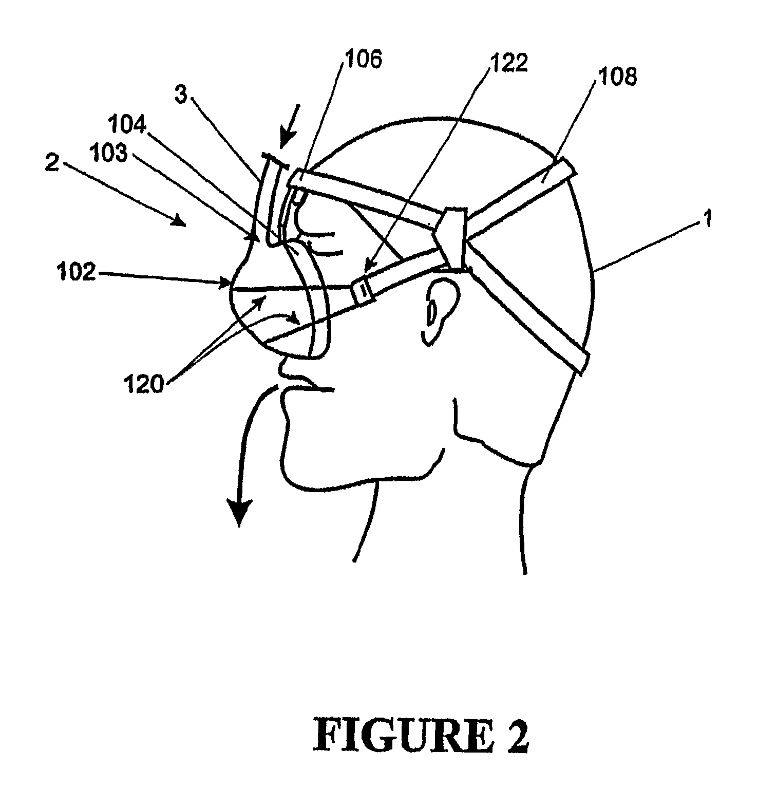
[0055]According to the present invention the patient interface is shown in FIG. 2 as a nasal mask. The mask includes a hollow body 102 with an inlet 103 connected to the inspiratory conduit 3. The mask 2 is positioned around the nose of the patient 1 with the headgear 108 secured around the back of the head of the patient 1. The restraining force from the headgear 108 on the hollow body 102 and the forehead rest 106 ensures enough compressive force on the mask cushion 104, to provide an effective seal against the patient's face.

[0056]The hollow body 102 is constructed of a relatively inflexible material for example, polycarbonate plastic. Such a material would provide the requisite rigidity as well as being transparent and a relatively good insulator. The expiratory gases can be expelled through a valve (not shown) in the mask, a further expiratory conduit (not shown), or any other such method as is known in the art.

Mask Cushion

[0057]Referring now to FIGS. 3 and 4 in particular, the...

second embodiment

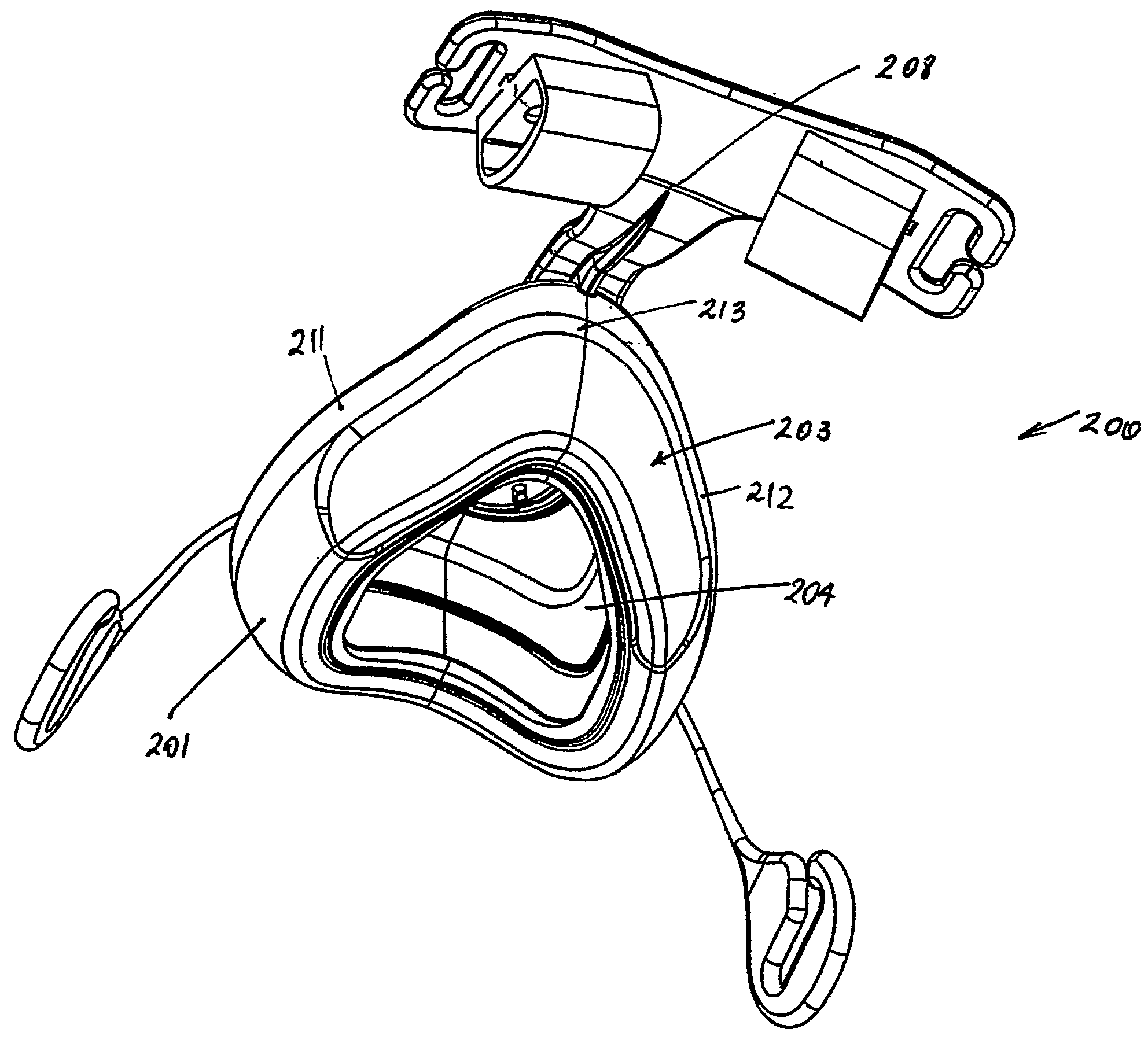
[0061]A second preferred embodiment to the mask cushion is depicted in FIGS. 9 and 10. In the second embodiment the inner cushion 2000 includes a raised bridge 2002 in the nasal bridge region. The raised bridge 2002 can also be described as a cut out section made in the cushion. Also, the notch in the contacting portion (between the inner cushion and outer sheath) is less pronounced than proceeding embodiments. However, as the raised bridge 2002 is unsupported it is much more flexible and results in less pressure on the nasal bridge of the patient. The outer sheath 2004 contacts the inner cushion 2000 throughout the raised bridge 2002. The peaks 2005, 2007, 2009, 2011 in the inner cushion 2000 between each of the indented sections 2006, 2008 and the raised bridge 2002 contact the outer sheath 2004 and when in use the sheath 2004 contacts the facial contours of the patient in the regions of these peaks.

[0062]Referring particularly to FIG. 10 the inner cushion 2000 includes a cheek co...


PUM


Abstract

A breathing assistance apparatus is designed for use with delivery of respiratory gases to a patient. The breathing assistance apparatus includes a patient interface, having a body section adapted to cover the nose, or nose and mouth of a patient and a sealing interface. The sealing interface includes at least an outer sealing member. The outer sealing member is adapted to attach to the body section in a sealing manner and has a substantially thin section in at least its nasal bridge region. The thin section is substantially thinner than the rest of the outer sealing member.

Description

[0001]This application is a 371 of PCT / NZ2005 / 000062 filed on Mar. 30, 2005 which claims the foreign priority of New Zealand application No. 532108 filed on Apr. 2, 2004,BACKGROUND OF THE INVENTION[0002]1. Field of the Invention[0003]This invention relates to patient interfaces particularly though not solely for use in delivering CPAP therapy to patients suffering from obstructive sleep apnoea (OSA).[0004]2. Summary of the Prior Art[0005]In the art of respiration devices, there are well known variety of respiratory masks which cover the nose and / or mouth of a human user in order to provide a continuous seal around the nasal and / or oral areas of the face such that gas may be provided at positive pressure within the mask for consumption by the user. The uses for such masks range from high altitude breathing (i.e., aviation applications) to mining and fire fighting applications, to various medical diagnostic and therapeutic applications.[0006]One requisite of such respiratory masks has...

Claims


Application Information

Patent Timeline
Patent Type & Authority Patents(United States)
IPC IPC(8): A61M16/06
CPCA61M16/0616A61M16/0622A61M16/0633A61M16/06A61M16/109A61M16/1095A61M16/0066A61M16/0683A61M16/16A61M2205/3368
Inventor MCAULEY, ALASTAIR, EDWINMILIVOJEVIC, IVANSHOTBOLT, AIDAN, MARK
Owner FISHER & PAYKEL HEALTHCARE LTD
Why Eureka
Try Eureka