Fluid leak detector apparatus

a leak detector and flue gas technology, applied in the direction of measuring fluid loss/gain rate, valve type, valve operating means/releasing devices, etc., can solve the problems of multiple small leaks in the supply system, many go undetected for a long time, and every part of the plumbing system is a potential source of leaks, so as to prevent excessive water damage, indirect water conservation

Active Publication Date: 2016-03-29
NEW WORLD PRODS
View PDF23 Cites 29 Cited by
  • Summary
  • Abstract
  • Description
  • Claims
  • Application Information

AI Technical Summary

Benefits of technology

[0008]The leak detector apparatus of this invention is designed to primarily protect building structures from unexpected high water pressures that are in some cases the cause of broken pipes, lines and fixtures that subsequently cause water damage in homes and other buildings. It will also protect the structure from the abuse of water hammer effect and in some circumstances, replace or operate in tandem with an existing water pressure regulator. In addition to the additional safety aspect of preventing electric shocks from standing water due to accidental leaks, the system also enables substantial water conservation and monetary savings through the active use of water flow / pressure control with the advanced software of the electronic monitoring system and the additional benefit of preventing excessive water damage by limiting the amount of water flowing into the structure once a leak does occur by shutting off the water supply and thus indirectly conserving water.

Problems solved by technology

Supply systems can experience multiple small leaks for many reasons and many go undetected for long periods of time because the amount of water is usually small and in places not easily detected.
When parts age such can sometimes fail over an extended period of time.
Since there is no situation where a plumbing component gets better with age, every part of a plumbing system is a potential source for a leak.
Sometimes a fitting or a connecting line behind a wall will drip such a small amount of water that it can go undetected for long periods of time, months and even years.
Flow meters and switches that are used in existing prior systems cannot always pick up these small drips.
Water waste, higher water bills and mold come from the neglect of these small drips.

Method used


Image

  • Fluid leak detector apparatus
  • Fluid leak detector apparatus
  • Fluid leak detector apparatus

Examples


first embodiment

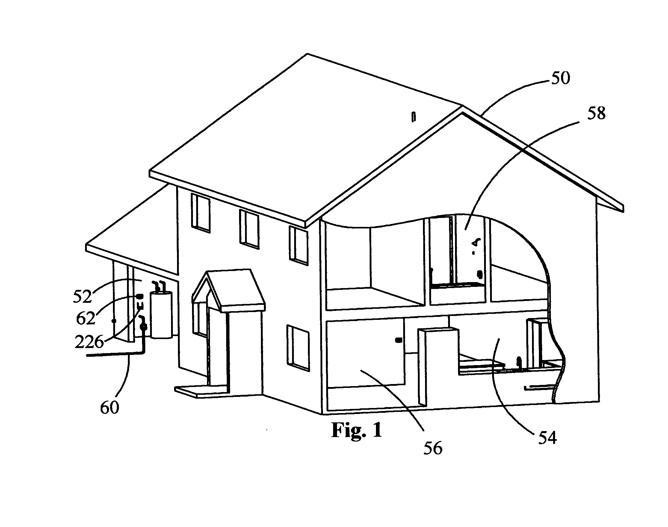
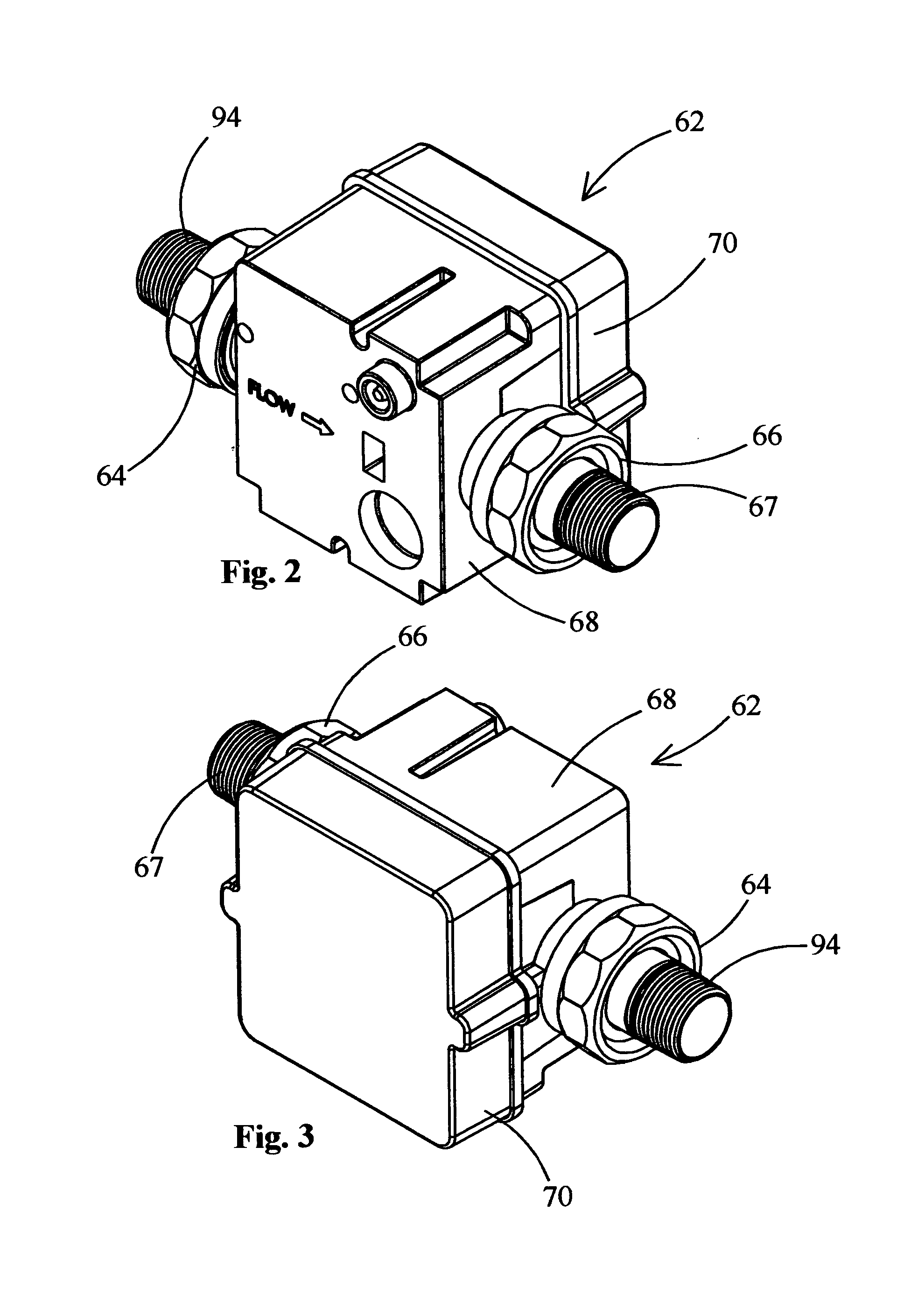
[0066]Referring particularly to FIG. 1 there is shown a building structure 50 which has a garage 52, a kitchen 54, a front room 56 and an upstairs area 58. A water supply pipe 60 is to supply water to the various outlets (not shown) located within the building structure 50 through a series of connecting lines. In the garage 52 there is to be installed within the water supply pipe 60 the regulator 62 of this invention. The regulator 62 is this invention. The water supply pipe 60 is to connect to regulator 62 by nipple 94 and fitting 64. A water outlet line (not shown) is to supply water to the various fixtures and appliances within the building structure 50 through connecting lines (not shown) and is connected by fitting 66 and nipple 67 to the outlet line.

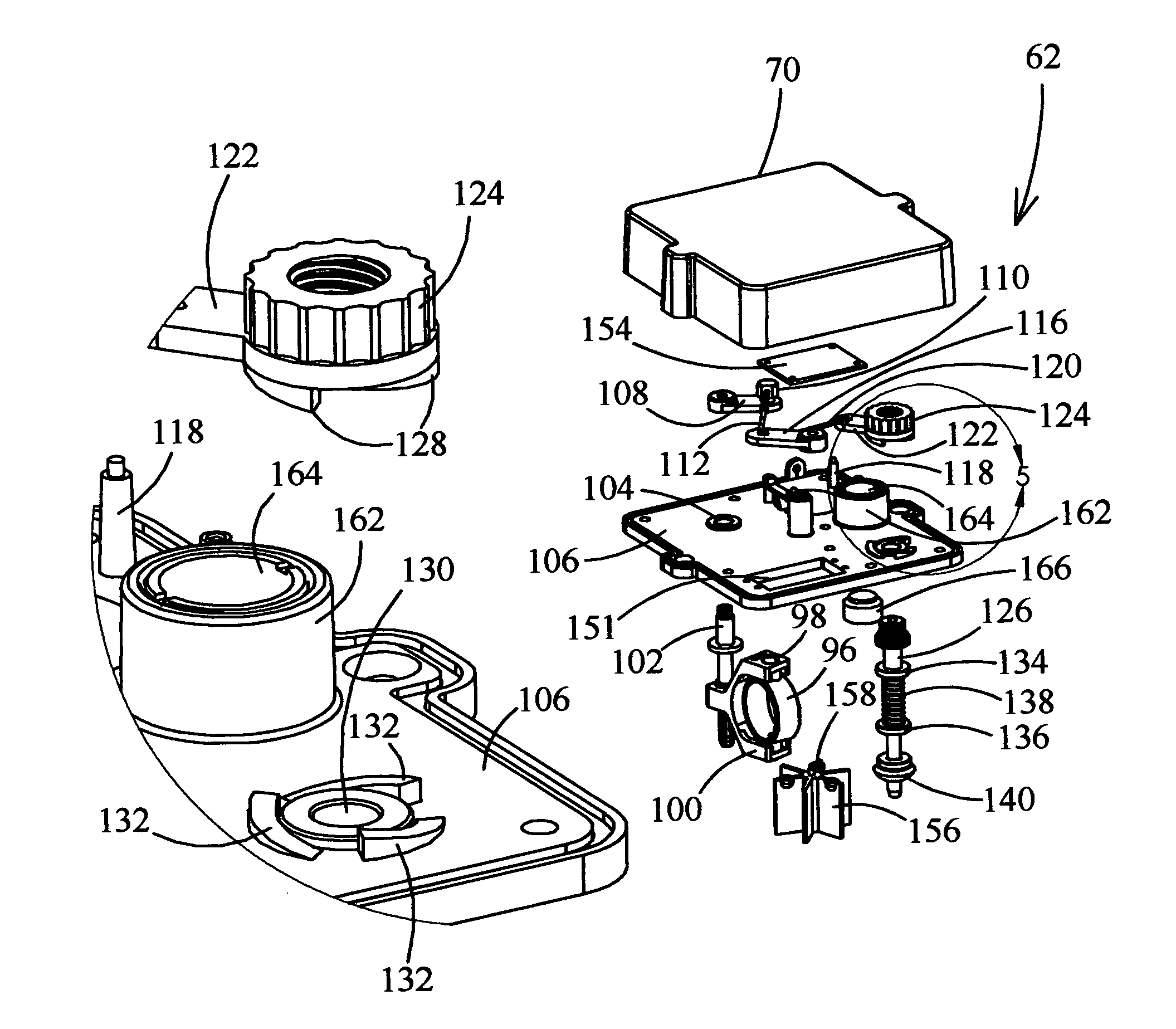
[0067]Regulator 62 has a housing comprised of a base 68 and a cover 70 which can normally be held together by a plurality of screws 72. Base 68 has an internal chamber 74. When cover 70 is mounted on base 68, internal chamber 74 is...

second embodiment

[0084]Referring particularly to FIGS. 38 to 44 there is shown flow control valve. There is a regulator 238 which is essentially similar to regulator 62. Regulator 238 has a housing 240 which is essentially similar to base 68. There will be a cover (not shown) utilized to enclose internal chamber 242, which is essentially identical to cover 70. Housing 240 has a pair of water passage openings with only opening 244 being shown. Nipple 246 connects with opening 244. The other opening connects with nipple 248. Nipple 246 is to connect with a water supply pipe (not shown) similar to water supply pipe 60. Nipple 248 connects with an outlet connecting line (not shown).

[0085]Internal chamber 242 includes partition walls 250 and 252. Between these walls there is a space within which is to be located a flow measuring device (not shown) similar to paddle wheel 156. The previously described bleed valve (126, 140, 146) is also included, and linked as described above. Located directly adjacent in...


PUM


Abstract

A leak detection apparatus which is to detect a fluid leak in a closed fluid system and produce a display of the information of the leak on a display window of a control panel which may also be programmed to transmit that information to the human user such as a cell phone. The leak detection apparatus can be located in a closed position, not permitting flow of fluid within the closed fluid system, or in an open position permitting flow of fluid into the closed fluid system. During inactivity the closed fluid system is not capable of receiving fluid from a fluid supply pipe. During activity when fluid is being normally discharged from the closed fluid system the leak detection apparatus is to receive fluid from the fluid supply pipe.

Description

BACKGROUND OF THE INVENTION[0001]1. Field of the Invention[0002]This invention pertains to a fluid leak detector apparatus and more particularly to a system that monitors and detects pressure increases and decreases in a closed fluid system for the purpose of discovering a leak.[0003]2. Background of the Invention[0004]The subject matter of this invention is of particular utility to a water plumbing system for a building structure such as a house or commercial building where water is conducted from a supply pipe to discharging fixtures within, on or directly adjacent the building structure. The water from the supply pipe is to be supplied to discharging fixtures such as faucets. The plumbing system will be described here as a normally closed liquid system which is pressurized but not discharging water when inactive, but which can be opened to discharge water through faucets and other fixtures during operation. Also, although this invention is described in relation to water, this inv...

Claims


Application Information

Patent Timeline
Patent Type & Authority Patents(United States)
IPC IPC(8): F16K31/48F16K17/36
CPCF16K17/36Y10T137/86389Y10T137/7761G01M3/28
Inventor GOSECO, JOHN, O.
Owner NEW WORLD PRODS
Why Eureka
Try Eureka