Structure for attaching service plug

a technology for service plugs and structures, applied in the direction of current conducting connections, electrical apparatus, cell components, etc., can solve the problems of restricted service plug shape, achieve the effect of preventing simultaneous rotation of respective terminals, improving workability of connecting terminals to battery electrodes, and improving workability

Active Publication Date: 2016-03-29
YAZAKI CORP
View PDF31 Cites 1 Cited by
  • Summary
  • Abstract
  • Description
  • Claims
  • Application Information

AI Technical Summary

Benefits of technology

[0009]An object of the present disclosure is to improve the workability of connecting each terminal to the electrode to be connected with the service plug.
[0011]According to the above configuration, when the pair of connection terminals for connecting the service plug is connected to the positive electrode and the negative electrode of the pair of adjacent batteries, even if the respective terminals are not held by a hand or the like for the purpose of preventing the simultaneous rotation, the protrusions are abutted against the respective terminals so as to prevent the simultaneous rotation of the respective terminals. Therefore, the workability of connecting the terminals to the electrodes of the battery connected with the service plug can be improved.
[0012]For example, the protrusions are walls which are provided so as to face each other at a distance corresponding to a width of each of the connection terminals, and each of the connection terminals is arranged on a space between the walls. As a result, since the respective terminals are abutted against the walls so as to stop the simultaneous rotation even if the respective terminals are going to rotate simultaneously with the nuts by bolting, the simultaneous rotation of the respective terminals can be prevented.
[0013]For example, ribs are protruded from facing surfaces of the walls, and the connection terminals are arranged between the ribs and an installation surface of the insulating substrate where the connection terminals are installed. According to this configuration, even if the respective terminals are going to be escaped from the space between the walls by some external force, since the ribs are abutted against the respective terminals so as to prevent the respective terminals from being escaped, the workability of connecting the terminals to the electrodes of the battery can be further improved.
[0014]For example, a protrusion to be engaged with a slit formed in each of the connection terminals is provided on at least one of the insulating substrate and the walls. According to this configuration, when the slit of each of the terminals is engaged with the protrusion, the terminals can be positioned, and the terminals can be prevented from moving away from the insulating substrate. Therefore, the workability of connecting the terminals to the electrodes of the battery can be still further improved.
[0015]According to the present disclosure, the workability of connecting each terminal to the electrode to be connected with the service plug can be improved.

Problems solved by technology

Also, there arises such a problem that a shape of the service plug is restricted due to the position where the service plug is attached.

Method used


Image

  • Structure for attaching service plug
  • Structure for attaching service plug
  • Structure for attaching service plug

Examples


Embodiment Construction

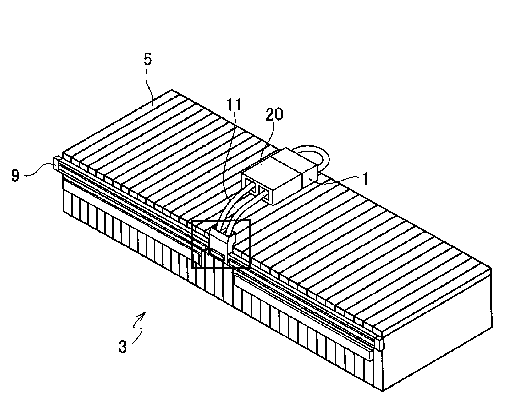
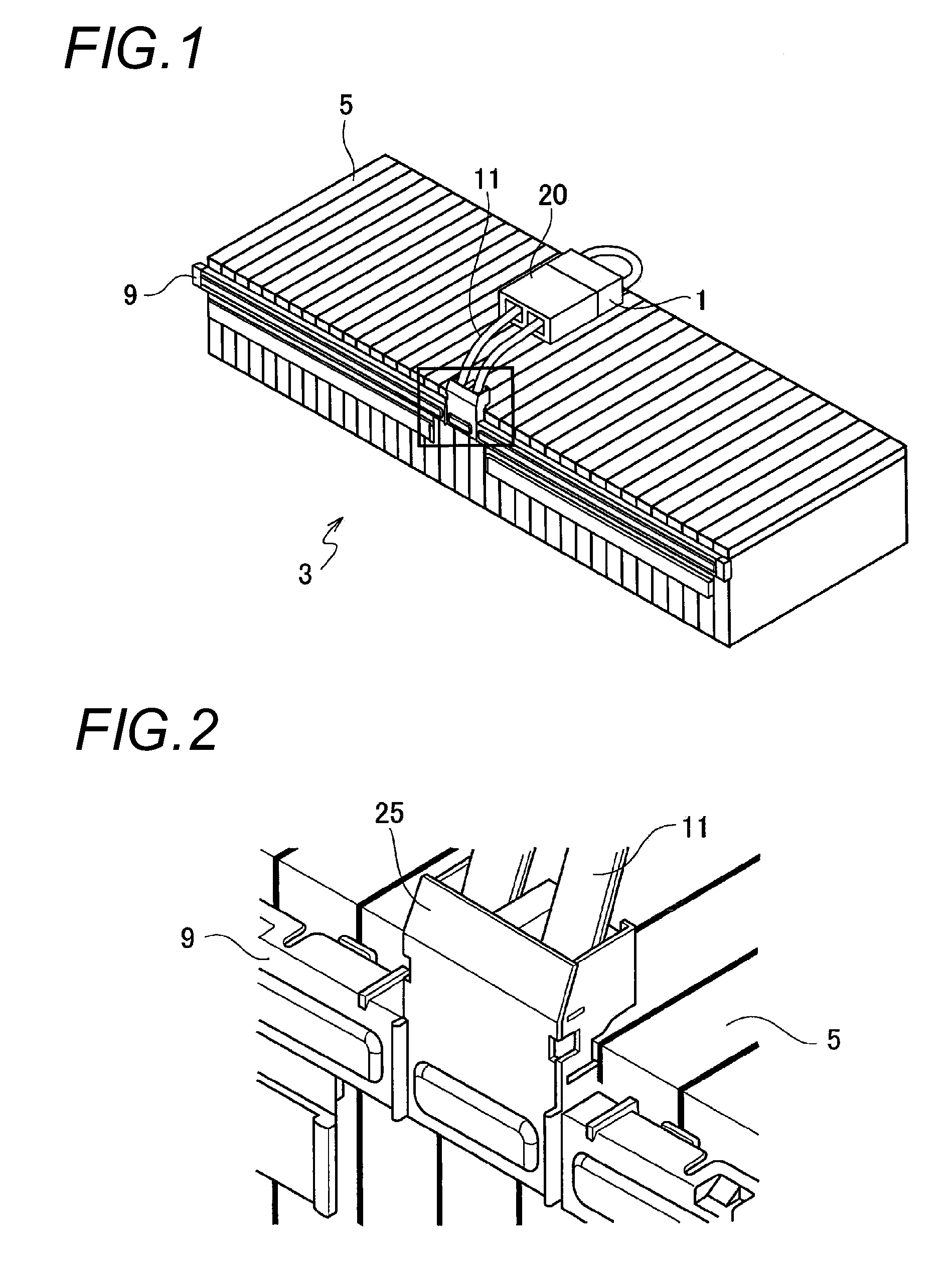
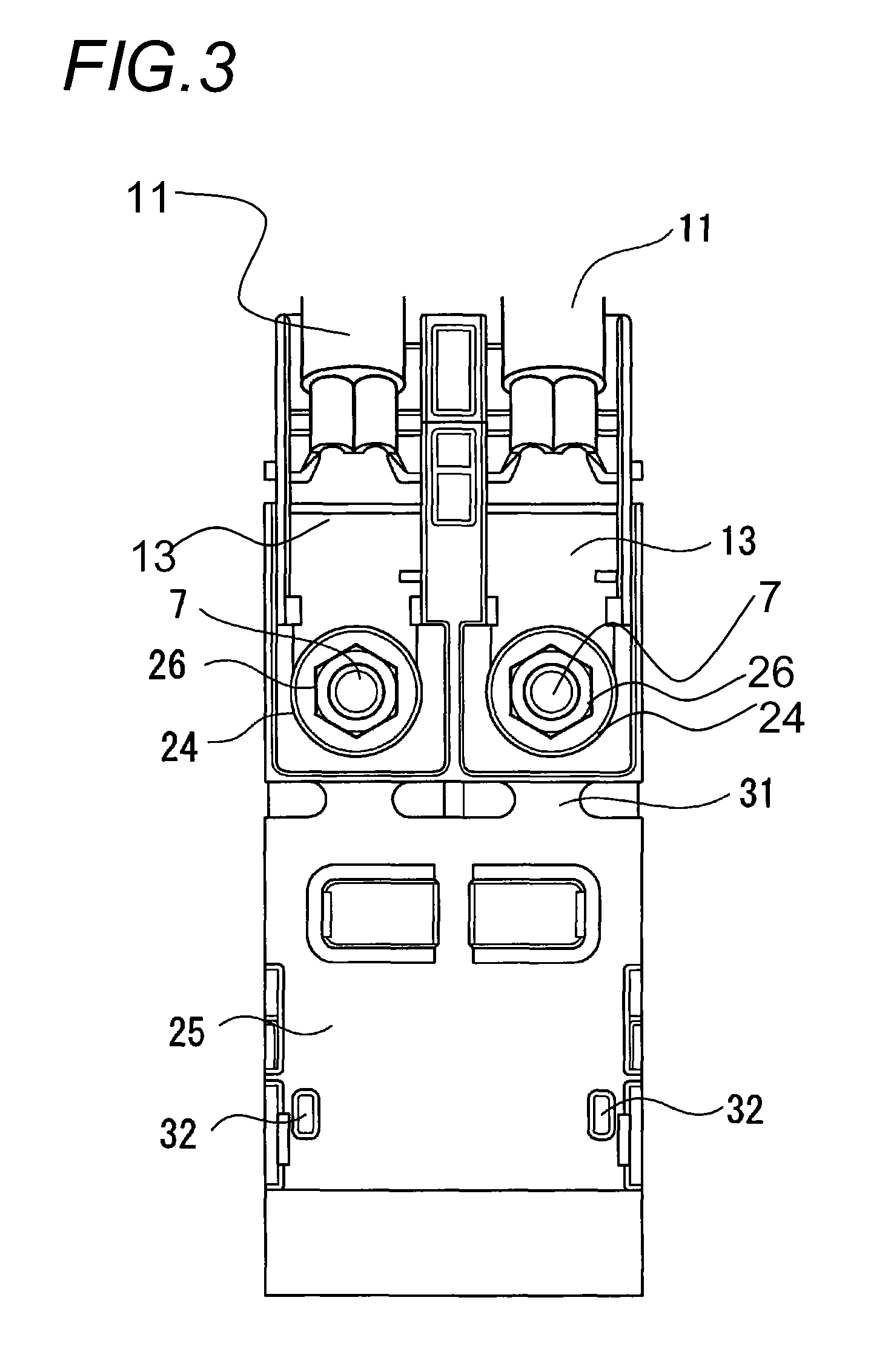
[0024]Hereinafter, an embodiment of the present disclosure will be described. As illustrated in FIGS. 1 to 6, a battery module 3 to which a service plug 1 is fixed according to this embodiment is configured such that positive electrodes and negative electrodes of a plurality of batteries 5 are alternately arranged, and the positive electrodes and the negative electrodes of the adjacent batteries 5 are connected to each other by a plurality of conductors, for example, a plurality of busbars. For example, a threaded columnar terminal portion 7 is protruded from each of the positive electrode and the negative electrode of each battery 5. The plurality of busbars is each housed and fixed in a busbar module 9. Each of the busbars is formed with a pair of insertion holes into which a pair of the terminal portions 7 of the adjacent batteries 5 is inserted. The terminal portions 7 are inserted into the respective insertion holes, and the positive electrode and the negative electrode of the ...


PUM

PropertyMeasurementUnit
widthaaaaaaaaaa
insulatingaaaaaaaaaa
shapeaaaaaaaaaa

Abstract

A structure for attaching a service plug includes an insulating substrate that has openings facing electrodes of a pair of adjacent batteries among a plurality of batteries in a battery module, a pair of connection terminals that are respectively connected to electrodes of the pair of adjacent batteries through the insulating substrate by bolting with nuts, a pair of electric wires whose one ends are connected to the connection terminals respectively, and a connector that is connected to the other ends of the pair of electric wires, and detachably connected with the service plug. The insulating substrate has protrusions which are abutted against the connection terminals respectively, and regulate movement of the connection terminals which simultaneously rotate with rotation of the nuts respectively when being bolted with the nuts.

Description

CROSS REFERENCE TO RELATED APPLICATIONS[0001]This application is a continuation of PCT application No. PCT / JP2012 / 069059, which was filed on Jul. 20, 2012 based on Japanese Patent Application (No. P2011-160603) filed on Jul. 22, 2011, the contents of which are incorporated herein by reference.BACKGROUND OF THE INVENTION[0002]1. Field of the Invention[0003]The present disclosure relates to a structure for attaching a service plug, and more particularly to a structure for attaching a service plug that opens and closes a power circuit of a battery module having a plurality of batteries connected in series.[0004]2. Description of the Related Art[0005]For example, JP-A-2002-343331 has proposed that when a battery module having a plurality of batteries connected in series is used in a power supply for driving an automobile, a series connection of a pair of positive and negative electrodes of the adjacent batteries is opened in advance, and a service plug is detachably connected between th...

Claims


Application Information

Patent Timeline
Patent Type & Authority Patents(United States)
IPC IPC(8): H01M2/34H01M2/20H01M50/50H01M50/503
CPCH01M2/34H01M2/20H01M2/202H01M50/50H01M50/503Y02E60/10
Inventor FURUYA, YOSHINOBUOGASAWARA, SHIGEYUKIINOUE, HIDEKI
Owner YAZAKI CORP
Why Eureka
Try Eureka