Ophthalmic apparatus, and treatment site measuring method for the apparatus

a technology of ophthalmic equipment and measuring method, which is applied in the field of ophthalmic equipment and measuring methods, can solve the problems of difficult to check that the location viewed through the view finder corresponds to the location of the entire retina, and it is difficult to move the visual field of the view finder to the operation location, etc., to achieve the effect of accurate treatment location of the eyeball

Active Publication Date: 2016-04-05
LUTRONIC VISION INC
View PDF7 Cites 7 Cited by
  • Summary
  • Abstract
  • Description
  • Claims
  • Application Information

AI Technical Summary

Benefits of technology

[0008]An object of the present invention is to provide an ophthalmic apparatus having an improved structure and method for associating the fundus oculi region of the retina with a local region of the retina viewed by an operator so that the operator can easily secure the visual field of a treatment location and methods of measuring, by the ophthalmic apparatus, a treatment location.
[0026]The ophthalmic apparatus and the methods of measuring, by the ophthalmic apparatus, a treatment location according to the present invention are advantageous in that an accurate treatment location of an eyeball on which an operator wants to perform a treatment process can be measured because an image of a local region of the retina viewed by the operator and generated by the second image unit can be mapped to an image of the retina generated by the first image unit.

Problems solved by technology

However, the technical characteristic disclosed in the conventional prior document may have a problem in that it is difficult to measure a more accurate location of the retina because it uses a method of displaying a retinal image without photographing the fundus oculi region of the retina.
Furthermore, an image recognized by an operator through a view finder is limited to a local portion of a retinal image, which makes it difficult to check that a location viewed through the view finder corresponds to which location of the entire retina.
Accordingly, if an operator lacks of experience, it is frequently difficult to move a visual field of the view finder to an operation location.

Method used


Image

  • Ophthalmic apparatus, and treatment site measuring method for the apparatus
  • Ophthalmic apparatus, and treatment site measuring method for the apparatus
  • Ophthalmic apparatus, and treatment site measuring method for the apparatus

Examples


first embodiment

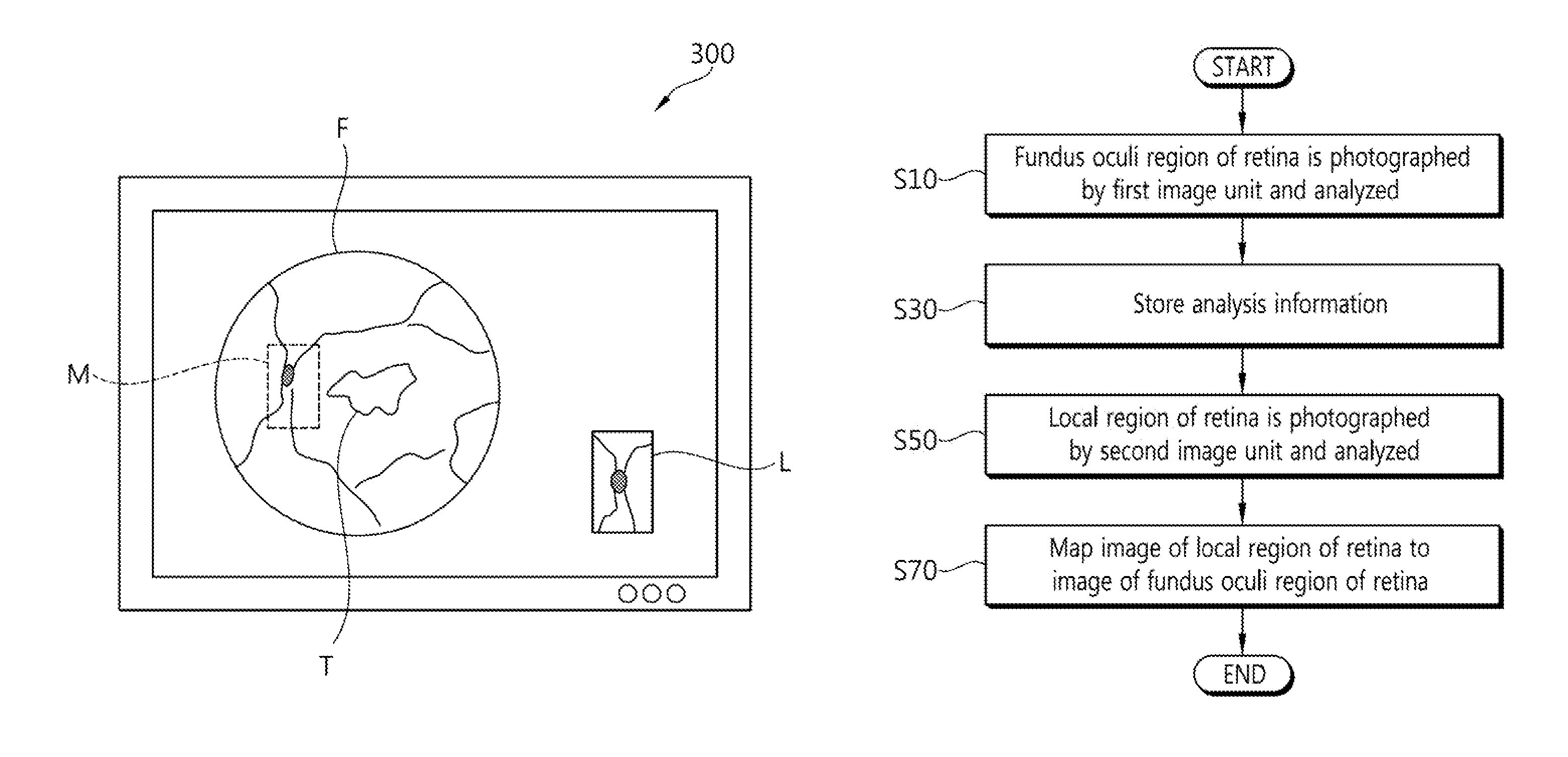
[0049]The method of measuring, by the ophthalmic apparatus 10 configured as described above, a treatment location in accordance with the present invention is described below with reference to FIG. 3.

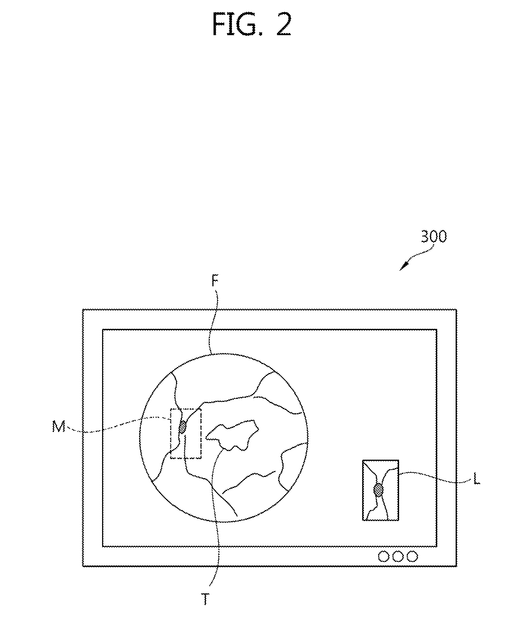
[0050]First, the first image unit 100 operates and generates the image F of a fundus oculi region of the retina by photographing the fundus oculi region of the retina. The generated image F of the fundus oculi region of the retina is analyzed (S10). Information about a specific region of the image F of the fundus oculi region of the retina analyzed by the image analysis unit 400 at step ‘S10’ is stored in the memory unit 500 (S30).

[0051]The second image unit 200 generates the image L of a local region of the retina by photographing the local region of the retina that is viewed by an operator (S50). The image L of the local region of the retina is mapped to the mapping location M in the image F of the fundus oculi region of the retina using the information stored in the memory unit 500.

[0...

second embodiment

[0056]The method of measuring, by the ophthalmic apparatus 10 configured as described above, a treatment location in accordance with the present invention is described below with reference to FIG. 5.

[0057]First, the first image unit 100 operates and generates the image F of the fundus oculi region of the retina by photographing the fundus oculi region of the retina. The generated image F of the fundus oculi region of the retina is analyzed (S100). Information about a specific region of the image F of the fundus oculi region of the retina analyzed by the image analysis unit 400 at step ‘S100’ is stored in the memory unit 500 (S300).

[0058]The second image unit 200 generates the image L of a local region of the retina by photographing the local region of the retina viewed by an operator (S500). The grids G are displayed in the image F of the fundus oculi region of the retina in order to improve efficiency of the mapping of the image L of the local region of the retina to the mapping lo...


PUM


Abstract

The present invention relates to an ophthalmic apparatus and to a treatment site measuring method for the apparatus. The ophthalmic apparatus according to the present invention comprises: a first image unit for capturing the lower region of a retina so as to generate an image of the captured retina; a second image unit for capturing the local region of the retina indicated by a surgical operator so as to generate an image of the captured local region of the retina; and a control unit for mapping the image of the local region of the retina generated by the second image unit to the image of the retina generated by the first image unit based on the image of the retina generated by the first image unit.

Description

BACKGROUND OF THE INVENTION[0001]1. Field of the invention[0002]The present invention relates to an ophthalmic apparatus and methods of measuring, by the ophthalmic apparatus, a treatment location and, more particularly, to an ophthalmic apparatus for measuring a lesion location of an eyeball and methods of measuring, by the ophthalmic apparatus, a treatment location.[0003]2. Related Art[0004]Types of ocular diseases include diseases, such as glaucoma in which intraocular pressure rises in the vitreous humour of an eyeball, a cataract in which a whitening phenomenon is generated in the crystalline lens, and macular degeneration generated in a retinal image that is focused.[0005]Recently, in order to treat ocular diseases, such as those described above, an ophthalmic treatment apparatus using a laser as a beam for treatment has emerged and the usability of the ophthalmic treatment apparatus is increasing. In order to treat ocular diseases using such an ophthalmic treatment apparatus,...

Claims


Application Information

Patent Timeline
Patent Type & Authority Patents(United States)
IPC IPC(8): A61B3/10A61B3/12A61B3/00A61B3/14G06T7/00
CPCA61B3/12A61B3/0058A61B3/14G06T7/0024A61B3/1233G06T2207/30041G06T2207/30096G06T7/30A61F9/00A61F9/007A61B3/0025
Inventor HA, TAE HOKIM, KI CHAN
Owner LUTRONIC VISION INC
Why Eureka
Try Eureka