Centrifuge with sliding carriages, and method for operating a centrifuge

a centrifuge and sliding carriage technology, applied in the direction of centrifuges, etc., can solve the problems of not being very versatile in the system, excessive braking is detrimental to the sample, and the remixing of the separated parts, so as to facilitate the transfer of samples

Active Publication Date: 2016-04-05
VERWEIJ WILLEM MARIUS
View PDF11 Cites 2 Cited by
  • Summary
  • Abstract
  • Description
  • Claims
  • Application Information

AI Technical Summary

Benefits of technology

[0012]The afore-mentioned centrifuge allows continuous operation using a relatively simple and cost-effective construction: first the shaft and the working section are rotated at a constant speed suitable for centrifugation. Then a carriage, for example containing test tubes with blood samples, can be attached to the acceleration member. Subsequently the auxiliary drive arrangement is used for accelerating the acceleration member to match the rotational speed of the working section after which the acceleration member is coupled to the working section via the loading end thereof. The carriage is then transferred from the acceleration member to the working section for being centrifuged, after which the acceleration member is decoupled from the working section. In order to unload the carriage from the working section the auxiliary drive arrangement is used for accelerating the deceleration member to match the rotational speed of the working section. Then the centrifuged carriage is transferred from the working section to the deceleration member via its unloading end, after which the deceleration member is decoupled from the working section. The deceleration member with the centrifuged carriage is then decelerated so that the carriage can be taken off. This centrifuge has a relatively simple and therefore relatively cheap construction and allows continuous loading and unloading of carriages.
[0023]A further embodiment foresees an assembly, wherein the carriage has a projecting part in the form of a screw for engagement with a groove of the working section, the acceleration member or the deceleration member. The screw-and-groove connection allows for a reliable connection necessary at high centrifugation speeds.

Problems solved by technology

Excessive braking is detrimental to the sample, and may lead to remixing of the separated portions.
Such systems are not very versatile and do not allow urgent samples to be handled.

Method used


Image

  • Centrifuge with sliding carriages, and method for operating a centrifuge
  • Centrifuge with sliding carriages, and method for operating a centrifuge
  • Centrifuge with sliding carriages, and method for operating a centrifuge

Examples


Embodiment Construction

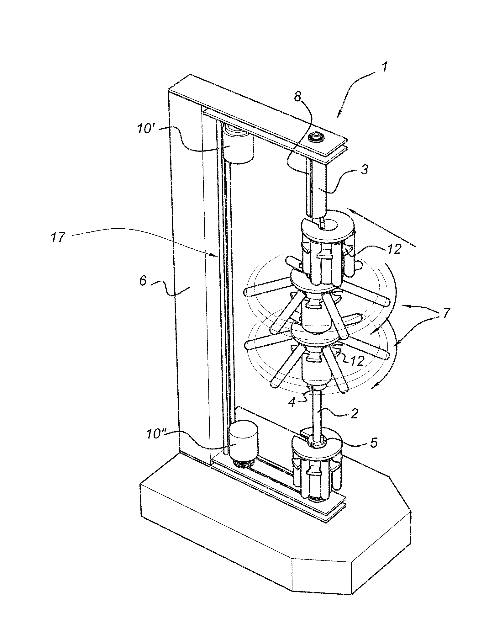
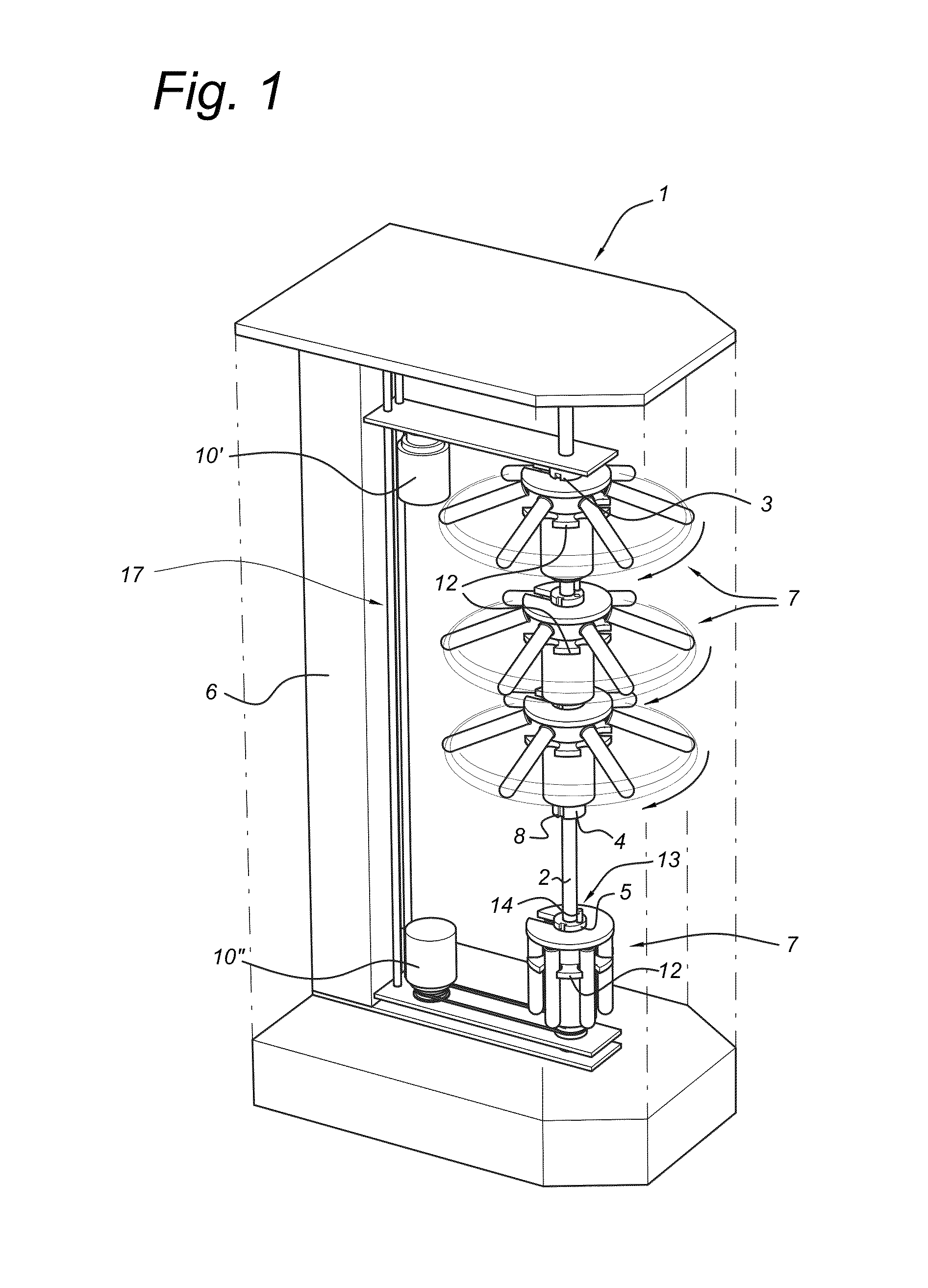
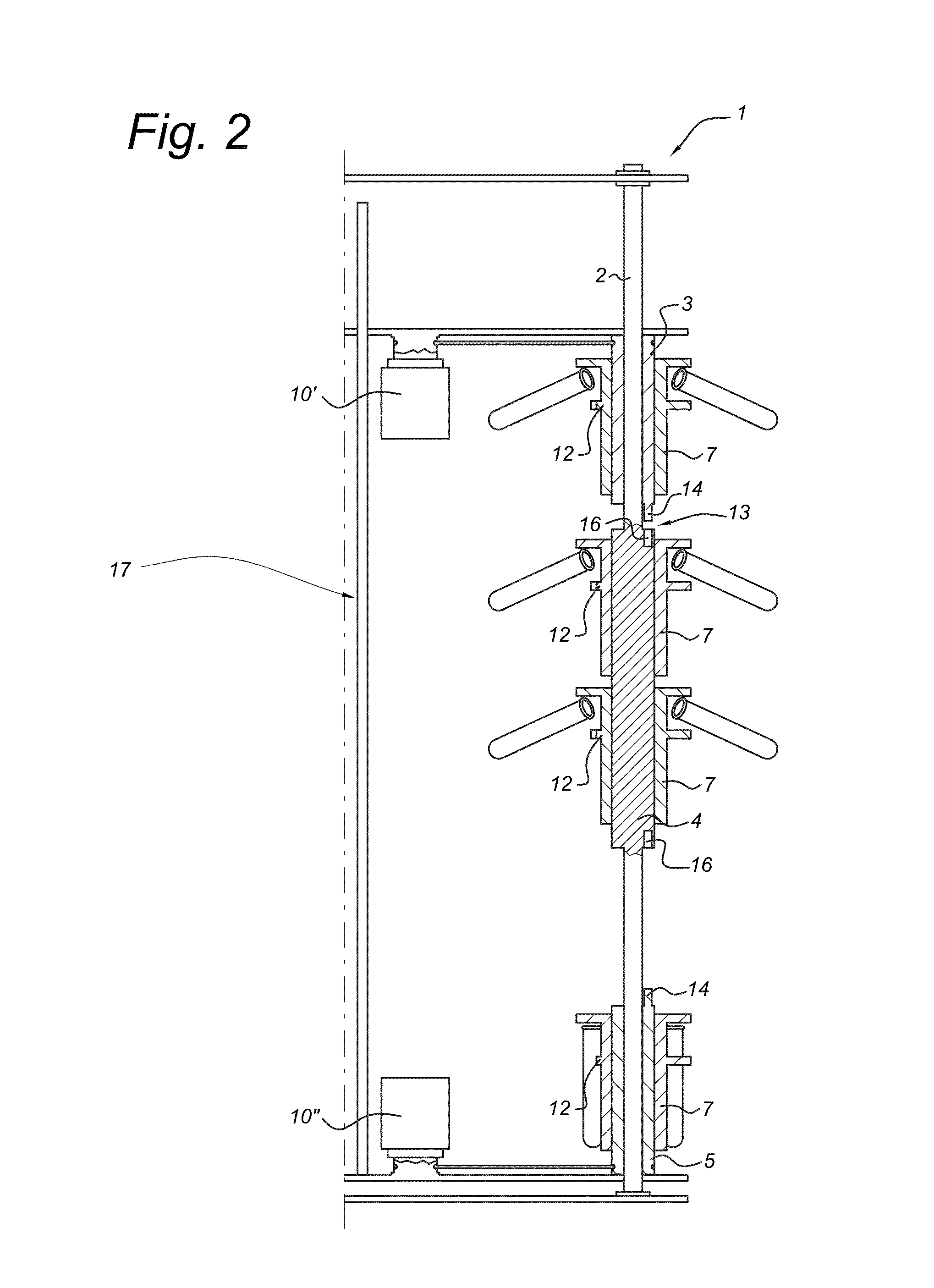
[0043]FIG. 1 shows a centrifuge 1 according to the invention in perspective view. The centrifuge 1 as shown in FIG. 1 comprises a shaft 2 rotatably mounted in a frame 6. The frame 6 is preferably arranged in a cabinet (schematically shown as dotted lines), with a door for loading and unloading, to prevent the formation of aerosols. The cabinet also serves to protect the rotating parts and allows for additional cooling of the centrifuge. During use the shaft 2 is preferably, but not necessarily, vertical as to allow smooth rotation of carriages 7. The shaft 2 can be hollow as to allow the accommodation of a co-rotating mechanism for fixation or manipulation of a carrier from the inside out. A central rotatable cylinder 4 is arranged on the shaft 2. The central rotatable cylinder 4 is rigidly connected to the shaft 2 such that when the shaft 2 is rotated the cylinder 4 also rotates at the same rotational speed. The shaft 2 is connected to a shaft drive motor (not shown). Above the cen...


PUM


Abstract

A centrifuge for high-speed centrifuging, includes: a shaft, mounted for continuous rotation about its axis, the shaft having a working section having a loading end and an unloading end; an acceleration member mounted adjacent to the loading end for rotation with respect to the shaft and; a deceleration member mounted adjacent to the unloading end for rotation with respect to the shaft; auxiliary drive arrangement for accelerating the acceleration member and the deceleration member to the shaft speed; carriages for supporting specimens for centrifugation. The carriages are slideably mounted for traversing from the acceleration member to the working section and from the working section to the deceleration member. A carriage may be accelerated on the acceleration member and then transferred to the working section for a period sufficient to perform centrifuging and then transferred from the working section to the deceleration member.

Description

FIELD OF THE INVENTION[0001]The present invention relates to a centrifuge for high-speed centrifugation of, for example, test tubes, in particular test tubes containing blood samples.BACKGROUND OF THE INVENTION[0002]In most laboratories, centrifugation takes place in a batch process, whereby a centrifuge is loaded with sample tubes and run up to speed. After a requisite period of steady state spinning, operation is stopped whereby the centrifuge must be allowed to run out slowly. Excessive braking is detrimental to the sample, and may lead to remixing of the separated portions. Once stopped, the centrifuge may be unloaded and a new batch prepared. Such systems are not very versatile and do not allow urgent samples to be handled.[0003]An example of such a centrifuge is given in U.S. Pat. No. 3,635,394. This publication shows a centrifuge, wherein the rotor must be decelerated or halted in order to load further samples or to unload centrifuged samples.[0004]It would be desirable to pr...

Claims


Application Information

Patent Timeline
Patent Type & Authority Patents(United States)
IPC IPC(8): B04B5/04B04B5/10B04B9/00B04B9/10
CPCB04B5/0414B04B5/10B04B9/00B04B5/0421B04B9/10
Inventor VERWEIJ, WILLEM MARIUS
Owner VERWEIJ WILLEM MARIUS
Why Eureka
Try Eureka