
Apparatus for forming a non-woven web

a technology of a non-woven web and an apparatus, which is applied in the direction of filament/thread forming, spinnerette pack, melt spinning method, etc., can solve the problems of filaments being larger, filaments being distorted, and/or forming rope defects

Active Publication Date: 2016-04-05
BIAX FIBERFILM CORP
View PDF25 Cites 12 Cited by
  • Summary
  • Abstract
  • Description
  • Claims
  • Application Information

AI Technical Summary

Benefits of technology

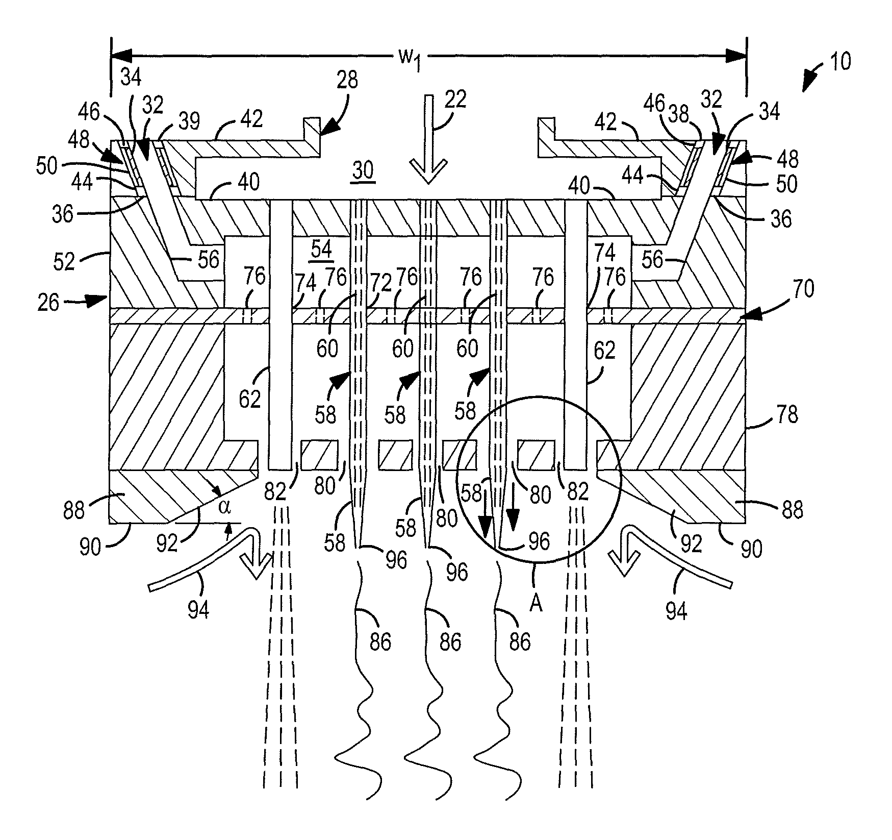
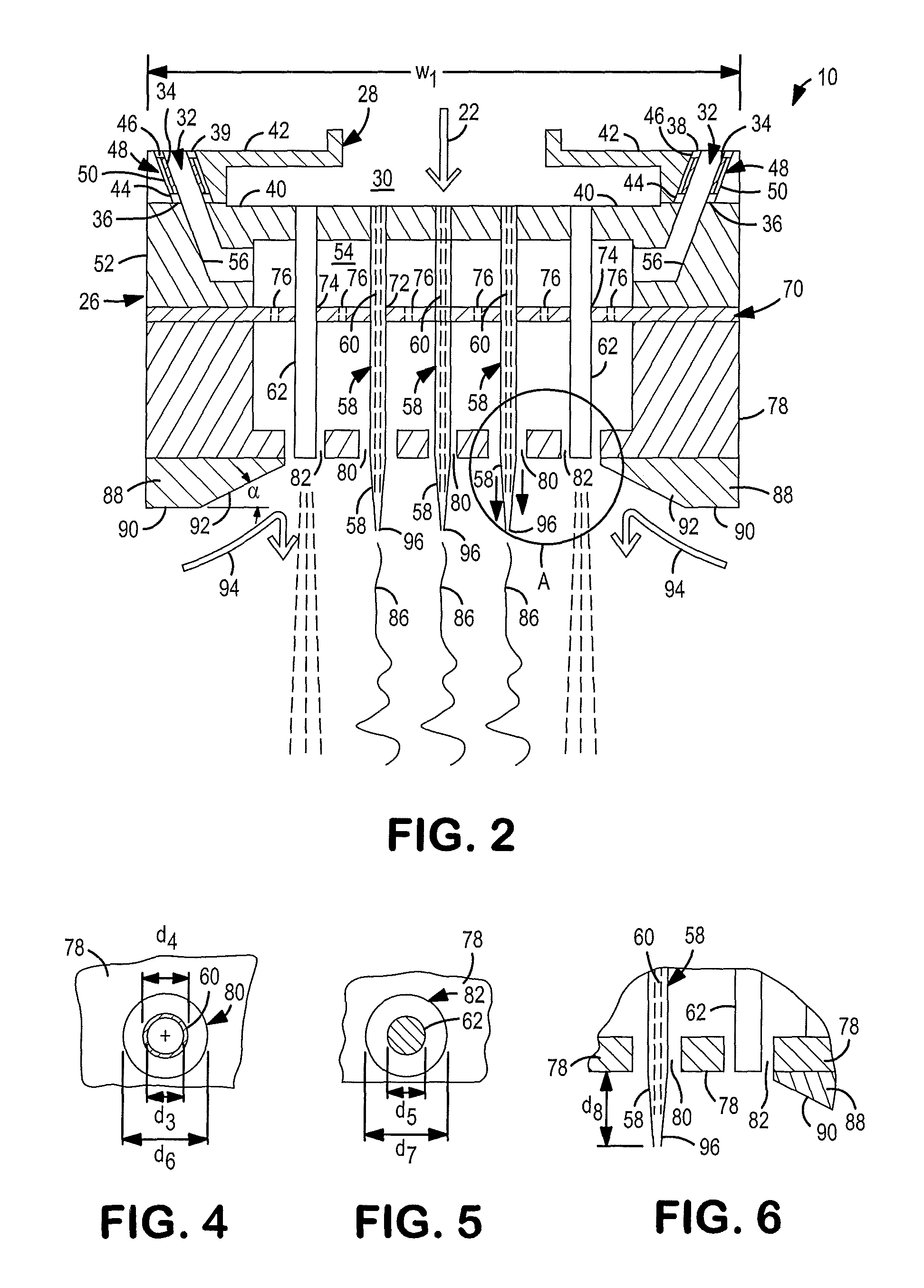
[0011]Still another object of this invention is to provide a die block where the incoming pressurized gas passages are thermally insulated from the remainder of the die block which allows for the use of gas having a colder temperature.

Problems solved by technology

However, meltblown fibers are relatively weak in strength.
In addition, spinning of thermoplastic resins through a multi-row spinnerette, according to the spinning technology taught in U.S. Pat. No. 5,476,616, is quite challenging because of the fast solidification of the outer rows and / or columns of filaments.
Due to this fast solidification in the outer rows and / or columns, the filaments tend to be larger and / or form rope defects with adjacent inner rows and / or columns of filaments.
The problem, up to now, is that no one has been able to find a way to extrude small fibers, having a diameter matching those of meltblown fibers, yet having the strength of spunbond fibers.

Method used


Image

  • Apparatus for forming a non-woven web
  • Apparatus for forming a non-woven web
  • Apparatus for forming a non-woven web

Examples


example 1

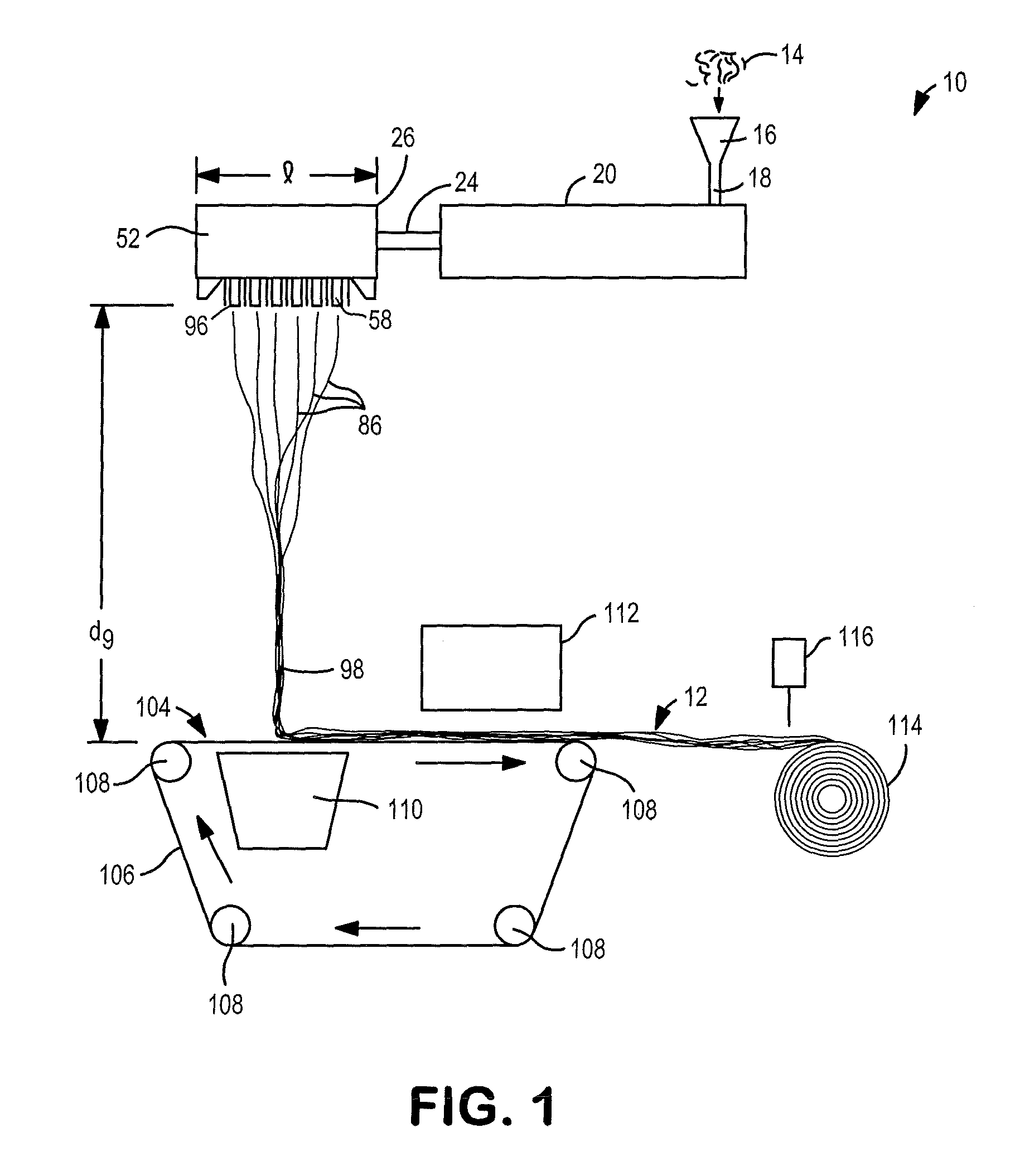
[0130]In this example, awe were looking at the effect of spinning technology on web properties. Three (3) different non-woven webs were made using the same polymer resin. All three (3) had the same basis weight but each was spun using a different spinnerette design and different processing conditions. As shown in Table 2, sample S-1 was produced using a Biax multi-row spinnerette design that did not have air insulation inserts 34 or an air shrouding curtain (second enlarged openings 82) surrounding the periphery 84 of the first enlarged openings 80. Sample S-2 was produced using a conventional meltblown process which had only one line of nozzles along with inclined air jets. Sample S-3 was produced using the inventive process.

[0131]The sample S-3 achieved almost double the machine direction (MD) tensile strength as compared to sample S-1 or sample S-2. Also, one will notice that the fiber diameter of sample S-3 was slightly larger than the fiber diameter of the conventional meltblow...

example 2

[0135]In this second example, we were comparing a sample produced by the inventive process S-5 to a sample produced by a conventional meltblown process S-4, and to sample produced by a conventional spunbond process S-6. Three (3) samples were made and each had the same basis weight. As shown in Table 3, the properties of sample S-5 were about half-way between the properties of the meltblown web S-4 and the spunbond web S-6. Table 3 also shows that the air permeability of the sample S-5 (using our inventive process) falls almost half-way between the conventional meltblown sample S-4 and the conventional spunbond sample S-6. This proves that our new technology is capable of producing non-woven webs that have fine fiber diameters, comparable to meltblown fibers, yet strong as compared to spunbond fibers.

[0136]Referring to FIG. 13, the machine direction (MD) tensile strength of the non-woven web 12 of this invention (sample S-5) was more than double the MD tensile strength of the meltbl...


PUM

PropertyMeasurementUnit
diametersaaaaaaaaaa
diameteraaaaaaaaaa
weightaaaaaaaaaa

Abstract

An apparatus is disclosed for forming a non-woven web.

Description

FIELD OF THE INVENTION[0001]This invention relates to an apparatus for forming a non-woven web.BACKGROUND OF THE INVENTION[0002]Meltblown fibers can be manufactured with very fine diameters, in the range of 1-10 microns, which is very advantageous in forming various kinds of non-woven fabrics. However, meltblown fibers are relatively weak in strength. To the contrary, spunbond fibers can be manufactured to be very strong but have a much larger diameter, in the range of 15-50 microns. Fabrics formed from spunbond are less opaque and tend to exhibit a rough surface since the fiber diameters are quite large. In addition, spinning of thermoplastic resins through a multi-row spinnerette, according to the spinning technology taught in U.S. Pat. No. 5,476,616, is quite challenging because of the fast solidification of the outer rows and / or columns of filaments. Due to this fast solidification in the outer rows and / or columns, the filaments tend to be larger and / or form rope defects with ad...

Claims


Application Information

Patent Timeline
Patent Type & Authority Patents(United States)
IPC IPC(8): D01D5/098D01D10/04D01D13/00D01D4/02D01D5/14D01D5/08
CPCD01D13/00D01D4/027D01D5/08D01D5/0985D01D5/14D01D10/0472D01D4/025
Inventor BROWN, DOUGLAS B.STARK, JEFFREY D.HASSAN, MOHAMMAD A.
Owner BIAX FIBERFILM CORP
Learn More