System, apparatus and method for automatically verifying exploits within suspect objects and highlighting the display information associated with the verified exploits

a technology of automatic verification and suspect objects, applied in the field of network security, can solve the problems of conventional ips technology suffering from a number, ips does not rely on any mechanism, and malicious software has become a pervasive problem for internet users

Active Publication Date: 2016-04-05
FIREEYE SECURITY HLDG US LLC
View PDF527 Cites 194 Cited by
  • Summary
  • Abstract
  • Description
  • Claims
  • Application Information

AI Technical Summary

Benefits of technology

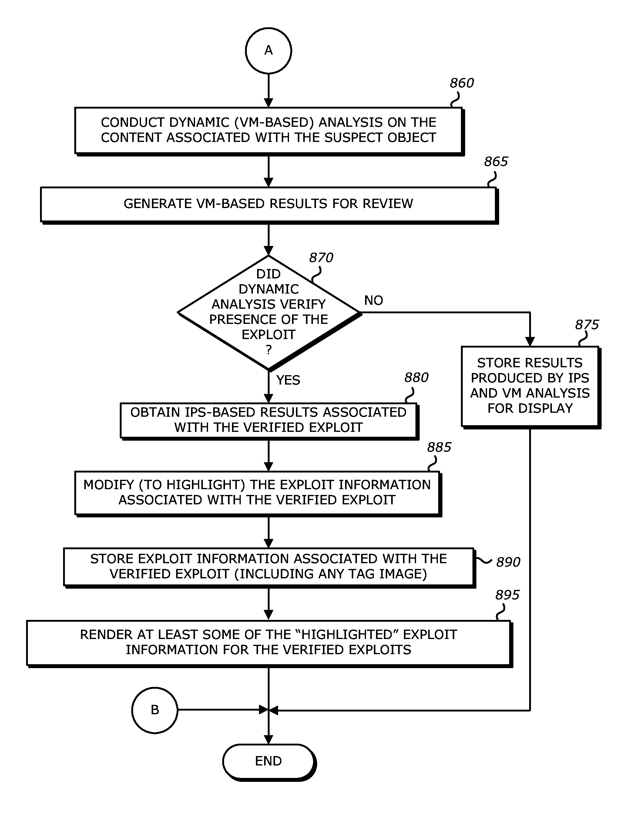
[0092]It is noted that the mere existence of a verified exploit may warrant heightened severity level, but does not require heightened severity levels as illustrated by the fact that certain non-verified exploits may be assigned higher severity levels than some verified exploits. Rather, exploit information associated with the verified exploits is highlighted, namely this exploit information is displayed more prominently than exploit information associated with non-verified exploits for example. This allows a network administrator to more quickly and easily determine verified exploits and thereby substantially mitigate administrative and operational disadvantages from false-positives.
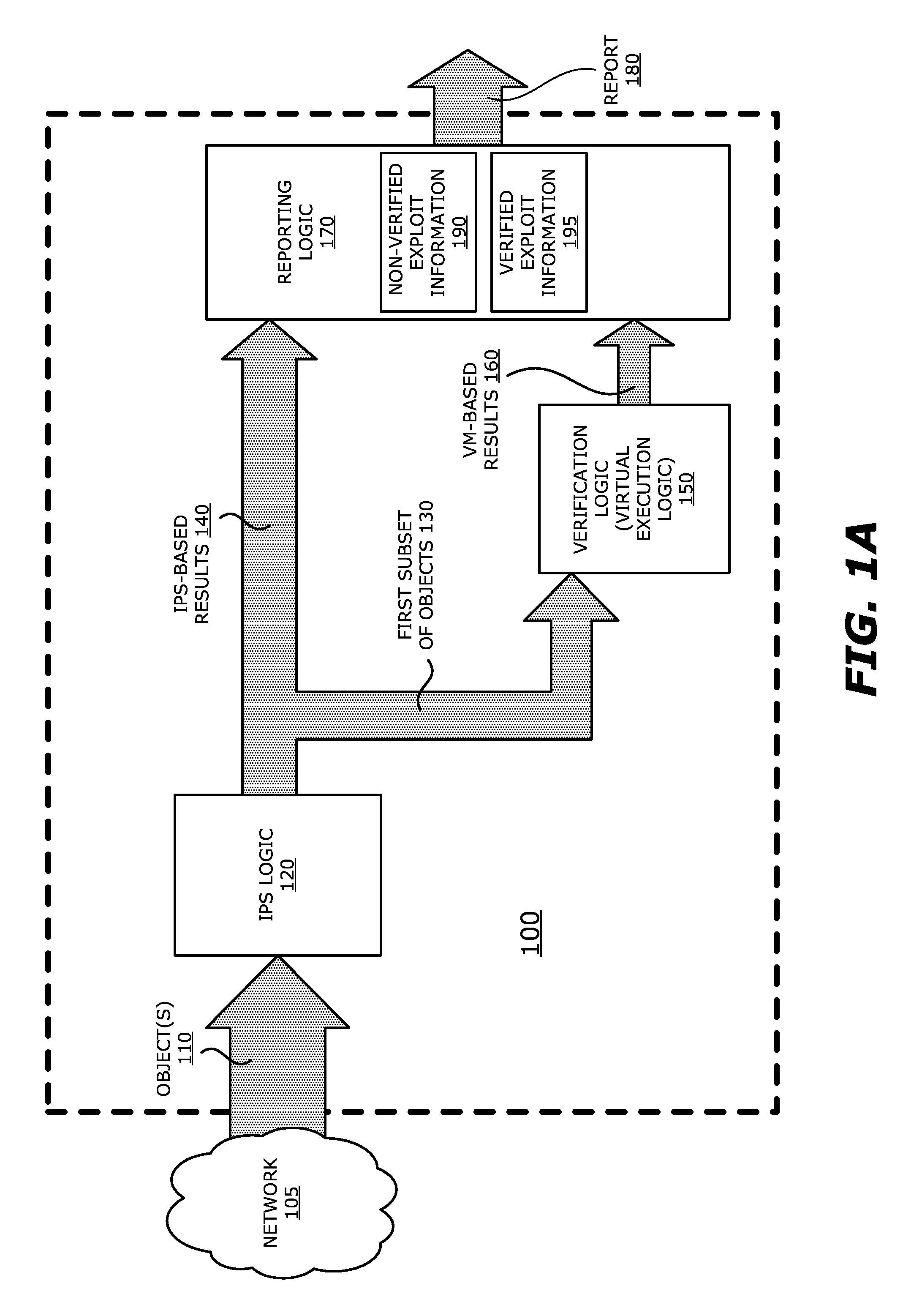
[0107]It is contemplated that the first static analysis logic (IPS logic) and the second static analysis logic (heuristic logic) may operate in parallel in which both of these logic units conduct the preliminary exploit detection analysis on the same suspect objects. More specifically, the second static analysis logic (heuristic logic) may conduct its analysis on an object extracted from the network traffic concurrently (i.e. at least partially overlapping in time) with the analysis of the same object by the IPS logic. This provides the TDP system with an ability to account for false negatives that signify a lack of detection of an exploit by the IPS logic. Also, such parallel analysis may be conducted in order to increase scrutiny of network traffic for objects originating from a certain geographic location prone to exploits, from a certain IP addresses that have been identified as a malicious source, or the like.

Problems solved by technology

Over the last decade, malicious software has become a pervasive problem for Internet users as most networked resources include software vulnerabilities that are subject to attack.
In general, an exploit is information that attempts to take advantage of a vulnerability in computer software by adversely influencing or attacking normal operations of a targeted computer.
However, conventional IPS technology suffers from a number of disadvantages.
One disadvantage with conventional IPS technology in that the IPS does not rely on any mechanism to automatically verify its results.
Another disadvantage is that, without automated verification, the IPS tends to produce a large number of false positives, namely incorrect alerts that occur when the IPS reports certain benign objects as exploits.
These false positives cause a variety of adverse effects.
For instance, due to the large number of false positives, one adverse effect is that actual exploits detected within network traffic may go unnoticed by an administrator.
Other adverse effects may include (i) needless blocking of incoming network traffic; (ii) unnecessarily reduction of processing resources; (iii) significant drainage of administrative resources to handle incorrectly classified objects; and (iv) development of a culture (or policy) of sporadically checking only some of the suspect objects.
In efforts to mitigate the number of false positives, the IPS may frequently require customized and periodic tuning of its signature database, which is a costly endeavor.
Furthermore, simply tuning the IPS to significantly reduce the number of false positives can severely degrade the effectiveness of the IPS and / or severely disrupt network operability.

Method used


Image

  • System, apparatus and method for automatically verifying exploits within suspect objects and highlighting the display information associated with the verified exploits
  • System, apparatus and method for automatically verifying exploits within suspect objects and highlighting the display information associated with the verified exploits
  • System, apparatus and method for automatically verifying exploits within suspect objects and highlighting the display information associated with the verified exploits

Examples


first embodiment

[0047]Referring to FIG. 2A, an exemplary block diagram of a communication system 200 deploying a plurality of threat detection and prevention (TDP) systems 2101-210N (N>1, e.g., N=3) communicatively coupled to a management system 220 via a network 225 is shown. In general, management system 220 is adapted to manage TDP systems 2101-2103. For instance, management system 220 is responsible for automatically updating one or more exploit signatures and / or vulnerability signatures used by IPS logic within some or all of TDP systems 2101-210N. Each of these signatures may represent a prior detected exploit or an uncovered software vulnerability. Such sharing may be conducted automatically or manually uploaded by an administrator. Also, such sharing may be conducted freely among the TDP systems 2101-2103 or subject to a subscription basis.

[0048]Herein, according to the embodiment illustrated in FIG. 2A, a first TDP system 2101 is an electronic device that is adapted to analyze information ...

second embodiment

[0075]Referring now to FIG. 2B, first TDP system 2101 may be coupled with the communication network 230 in line with client device 234. Contrary to the embodiment illustrated in FIG. 2A, first TDP system 2101 comprises an interface unit 295 that directs signaling on communication network 230 to static analysis engine 250 or classification logic 285, given that the dynamic analysis engine 270 is deployed in cloud computing services 240. Hence, objects from network traffic for static analysis are routed to static analysis engine 250 via communication path 296. The suspicious objects may be routed via path 297 to the dynamic analysis engine 270 in cloud computing services 240. Similarly, objects that are not determined to be at least “suspect” may be returned via path 297 for continued routing to client device 234. The results of the dynamic analysis engine 270 (e.g., exploit information) may be routed via path 298 for prioritization and tagging before storage within database 255 for s...


PUM


Abstract

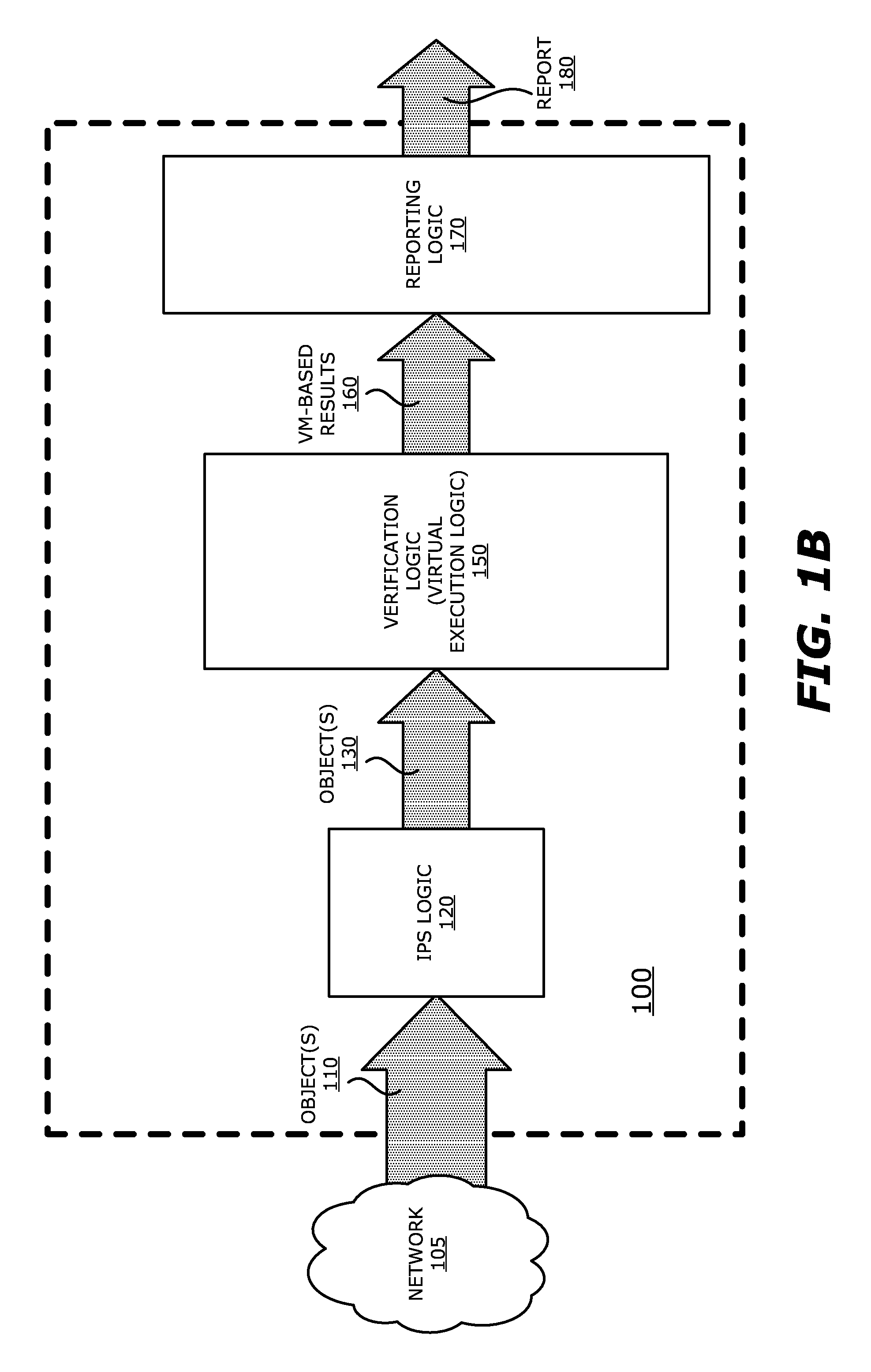
A threat detection system is integrated with intrusion protection system (IPS) logic, virtual execution logic and reporting logic is shown. The IPS logic is configured to identify a first plurality of objects as suspicious objects and outputting information associated with the suspicious objects. The virtual execution logic is configured to receive the suspicious objects and verify whether any of the suspicious objects is an exploit. The virtual execution logic includes at least one virtual machine configured to virtually process content within the suspicious objects and monitor for anomalous behaviors during the virtual processing that are indicative of exploits. The reporting logic is configured to issue a report including the information associated with the suspicious objects from the IPS logic and results of the virtual processing of the content within the suspicious objects.

Description

CROSS-REFERENCE TO RELATED APPLICATIONS[0001]This application is a divisional of U.S. patent application Ser. No. 14 / 228,073 filed Mar. 27, 2014, which claims the benefit of priority on U.S. Provisional Application No. 61 / 921,033, filed Dec. 26, 2013, the entire contents of both of which are incorporated by reference herein.FIELD[0002]Embodiments of the disclosure relate to the field of network security. More specifically, one embodiment of the disclosure relates to a system, apparatus and method for identifying a suspicious object, automatically verifying the suspect object as an exploit through virtual processing.GENERAL BACKGROUND[0003]Over the last decade, malicious software has become a pervasive problem for Internet users as most networked resources include software vulnerabilities that are subject to attack. For instance, over the past few years, more and more vulnerabilities are being discovered in software that is loaded onto network devices, such as vulnerabilities within ...

Claims


Application Information

Patent Timeline
Patent Type & Authority Patents(United States)
IPC IPC(8): G08B23/00H04L29/06G06F17/00
CPCH04L63/1491G06F21/564G06F21/566H04L63/1416H04L63/1433H04L63/145G06F9/45558G06F2009/45587G06F21/53G06F2221/033G06F21/56
Inventor AZIZ, ASHARAMIN, MUHAMMADISMAEL, OSMAN ABDOULBU, ZHENG
Owner FIREEYE SECURITY HLDG US LLC
Why Eureka
Try Eureka