Imaging apparatus and imaging method which perform focus adjustment while performing live-view display

a technology of live-view display and imaging apparatus, which is applied in the direction of color television details, television system details, television systems, etc., can solve the problems of user discomfort, inability to correct the image data obtained by afae into the image data having the same image quality, and change in image quality of live-view display

Active Publication Date: 2016-04-05
OLYMPUS CORP
View PDF3 Cites 4 Cited by
  • Summary
  • Abstract
  • Description
  • Claims
  • Application Information

AI Technical Summary

Benefits of technology

[0008]The present invention has been achieved in view of such a situation, and aims to provide an imaging apparatus and an imaging method which perform the live-view display by generating the image data using the exposure parameter calculated from the brightness value of the photometric area for the live-view display which is different from the photometric area for the focus adjustment when not performing the focus adjustment, and also can perform the focus adjustment in a high accuracy while performing the live-view display in a preferable image quality despite whether the focus adjustment is being performed or not when performing the live-view display also during the focus adjustment.

Problems solved by technology

For example, when, although the image data obtained by performing LVAE for some subject area does not reach a saturation level, the image data obtained by performing AFAE for the same subject area reaches the saturation level, it is not possible to correct the image data obtained by AFAE into the image data having the same image quality as that of the image data obtained by LVAE.
Accordingly, in such a case, even when the image data is corrected, the image quality of the live-view display still changes between before and after the focus adjustment, and thus the user feels uncomfortable.

Method used


Image

  • Imaging apparatus and imaging method which perform focus adjustment while performing live-view display
  • Imaging apparatus and imaging method which perform focus adjustment while performing live-view display
  • Imaging apparatus and imaging method which perform focus adjustment while performing live-view display

Examples


embodiment 1

[0020]In the following, preferred Embodiment 1 will be explained by the use of a camera to which the present invention is applied. Note that, in the following explanation, explanation or detailed explanation will be omitted for the same operation and control technique as those of a typical imaging apparatus.

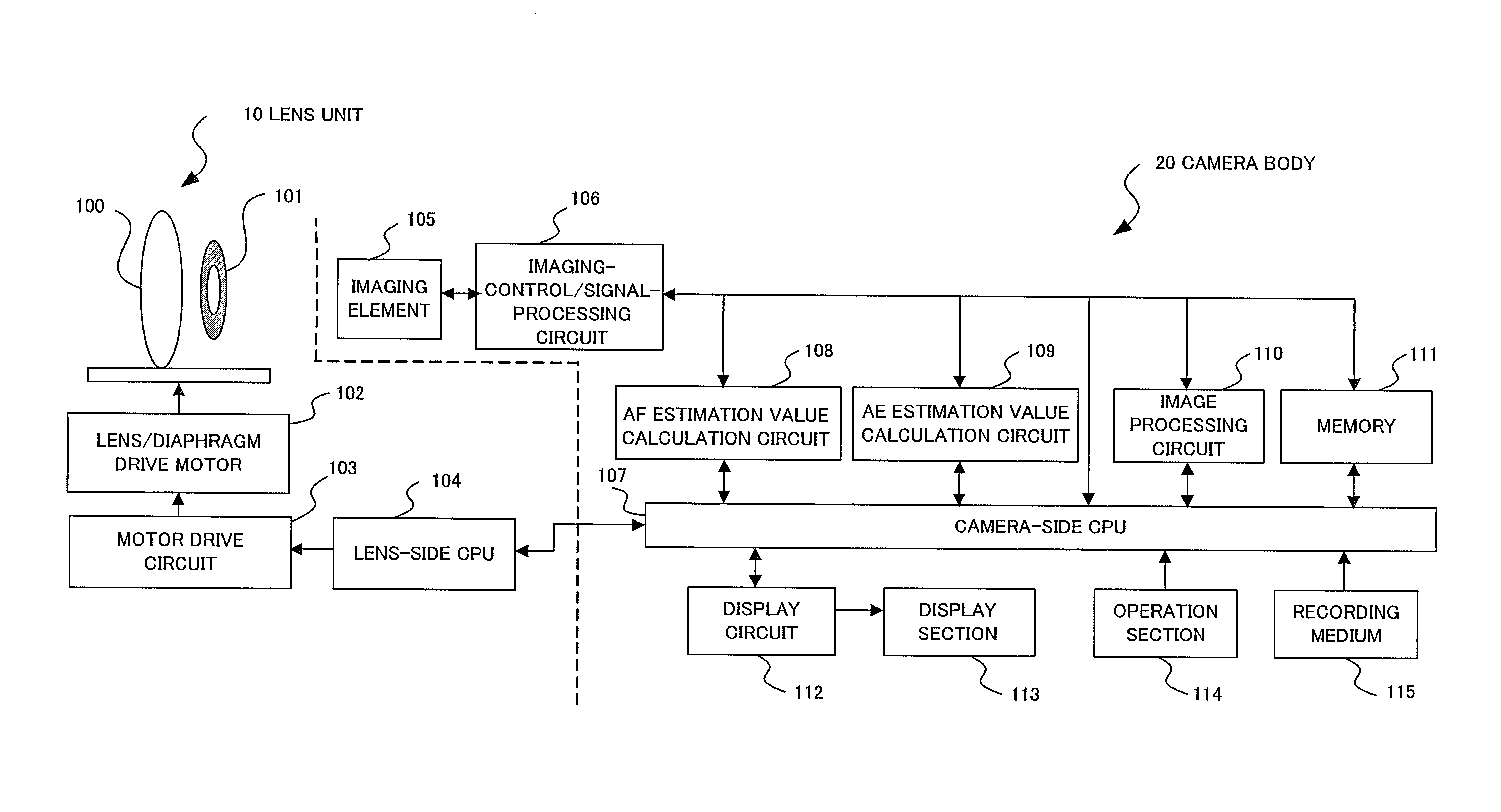
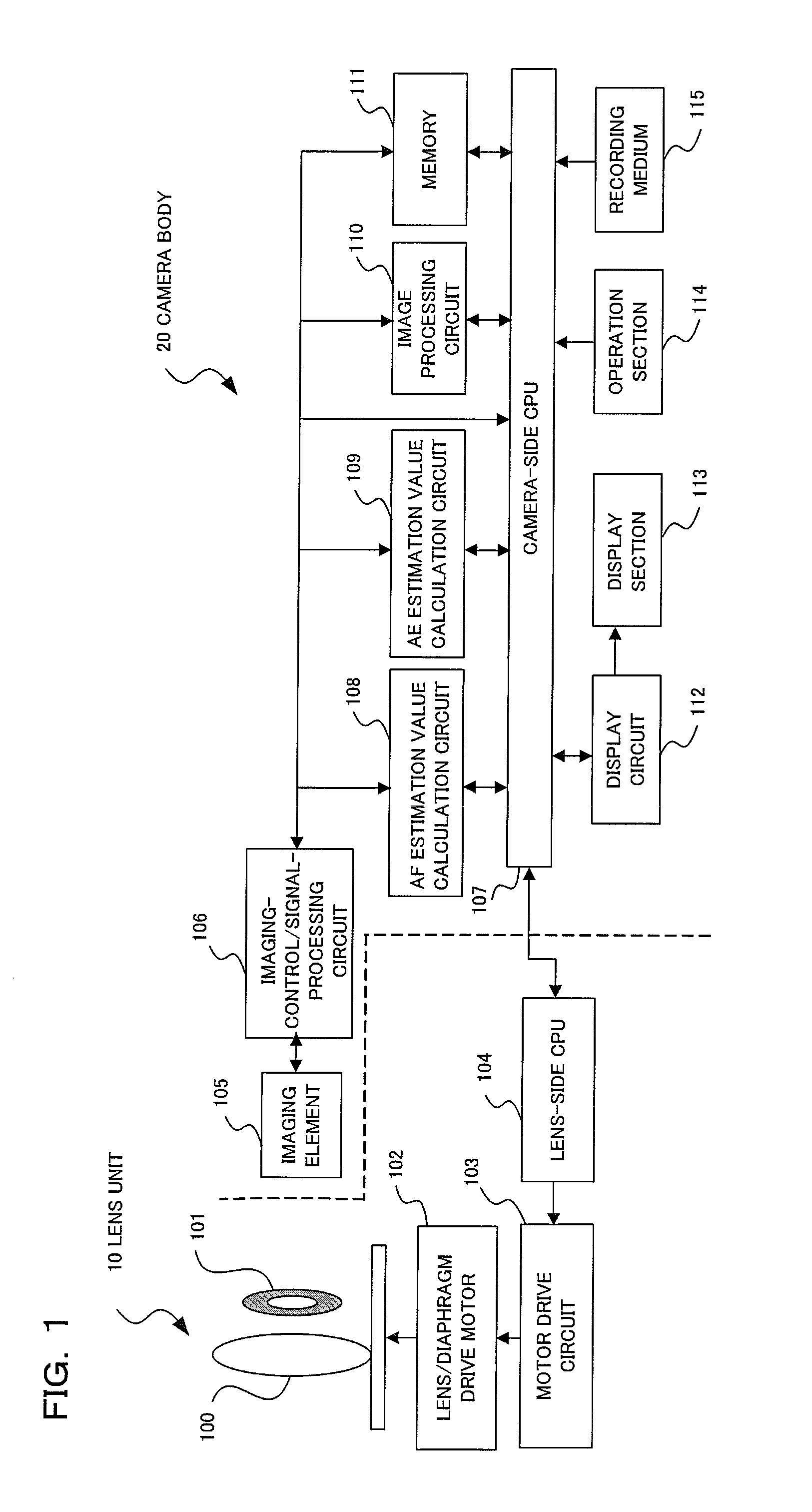
[0021]A camera according to Embodiment 1 is a digital camera, includes an imaging element 105, converts a subject image into image data in this imaging element 105, and displays the subject image on a display section in real time (hereinafter, called “live-view display”) according to this converted image data. In photographing, a photographer selects an area where a subject is to be focused (hereinafter, called “focus area”) and determines composition by observing the live-view display. When a release button included in an operation section 114 is half-pressed (hereinafter, called “1st release”), the focus of a photographic lens 100 is adjusted, and, when the release button is fu...

embodiment 2

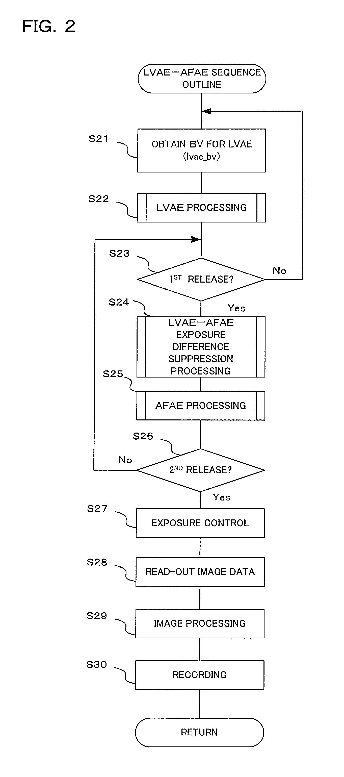
[0048]Embodiment 2 is different from Embodiment 1 only in the LVAE-AFAE exposure difference suppression processing of step S24 inFIG. 2. The other configuration and processing are the same as those in Embodiment 1, and only the different point will be explained in the following explanation.

[0049]FIG. 8 shows a relationship between the difference of the brightness of the focus adjustment photometric area from the brightness of the live-view display photometric area (delta_bv), and the correction value for correcting the brightness value of the live-view display photometric area to calculate the brightness value for performing the focus adjustment (bv_revise), in the present embodiment.

[0050]In the present embodiment, bv_revise is increased as the absolute value of delta_bv becomes larger when delta_bv is included in the range from the lower limit value track_limit_low to the upper limit value track_limit_hi. That is, lvae_bv is corrected and afae_bv is calculated so as to cause the d...

embodiment 3

[0052]Embodiment 3 is different from Embodiment 1 only in the LVAE-AFAE exposure difference suppression processing of step S24 in FIG. 2. The other configuration and processing are the same as those of Embodiment 1, and only the different point will be explained in the following explanation.

[0053]FIG. 9 shows a relationship between the difference of the brightness of the focus adjustment photometric area from the brightness of the live-view display photometric area (delta_bv), and the correction value for correcting the brightness value of the live-view display photometric area to calculate the brightness value for performing the focus adjustment (bv_revise), in the present embodiment.

[0054]In the present embodiment, when delta_bv is included in the range from the lower limit value track_limit_low to the upper limit value track_limit_hi, as the absolute value of delta_bv becomes larger, lvae_bv is corrected and afae_bv is calculated so as to cause the difference between lvae_bv and ...


PUM


Abstract

An imaging apparatus according to the present invention is an imaging apparatus performing live-view display when not performing the focus adjustment, and also when performing the focus adjustment, and includes: a focus adjustment brightness value calculation section comparing a first brightness value in the photometric area for the live-view display with a second brightness value in the photometric area for the focus adjustment, correcting the first brightness value according to a comparison result, and calculating a brightness value for obtaining the image data for the focus adjustment; an imaging section obtaining the image data by performing exposure using the brightness value calculated by the focus adjustment brightness value calculation section; a focus adjustment section performing the focus adjustment using the image data obtained by the imaging section, and a display section performing the live-view display using the image data obtained by the imaging section.

Description

[0001]Benefit is claimed, under 35 U.S.C. §119, to the filing date of prior Japanese Patent Application No. 2013-085772 filed on Apr. 16, 2013. This application is expressly incorporated herein by reference. The scope of the present invention is not limited to any requirements of the specific embodiments described in the application.BACKGROUND OF THE INVENTION[0002]1. Field of the Invention[0003]The present invention relates to an imaging apparatus and an imaging method which perform focus adjustment while performing live-view display.[0004]2. Description of Related Art[0005]There has been known a camera which performs exposure by setting an exposure parameter (exposure time, aperture value, etc.) calculated based on brightness in a predetermined photometric area of a subject, when performing normal live-view display without performing focus adjustment (hereinafter, such exposure is called “LVAE”), and which performs the exposure for obtaining image data for the focus adjustment by ...

Claims


Application Information

Patent Timeline
Patent Type & Authority Patents(United States)
IPC IPC(8): H04N5/232H04N5/222H04N5/235
CPCH04N5/2351H04N5/2352H04N5/23212H04N5/23293H04N23/72H04N23/71H04N23/73
Inventor ITO, SATORU
Owner OLYMPUS CORP
Why Eureka
Try Eureka