Hand brake device for a vehicle

a technology for hand brakes and vehicles, applied in mechanical control devices, process and machine control, instruments, etc., can solve problems such as the inability of the actuator to respond to the activation of the lever and the inability to tighten the brak

Active Publication Date: 2016-04-12
GM GLOBAL TECH OPERATIONS LLC
View PDF20 Cites 0 Cited by
  • Summary
  • Abstract
  • Description
  • Claims
  • Application Information

AI Technical Summary

Benefits of technology

[0004]In accordance with the present disclosure a hand brake device for a vehicle is provided with a brake to be activated

Problems solved by technology

When a user pulls up the brake lever, he or she can lock it into the brake position, but if the onboard electri

Method used


Image

  • Hand brake device for a vehicle
  • Hand brake device for a vehicle

Examples


Embodiment Construction

[0021]The following detailed description is merely exemplary in nature and is not intended to limit the present disclosure or the application and uses of the present disclosure. Furthermore, there is no intention to be bound by any theory presented in the preceding background or the following detailed description.

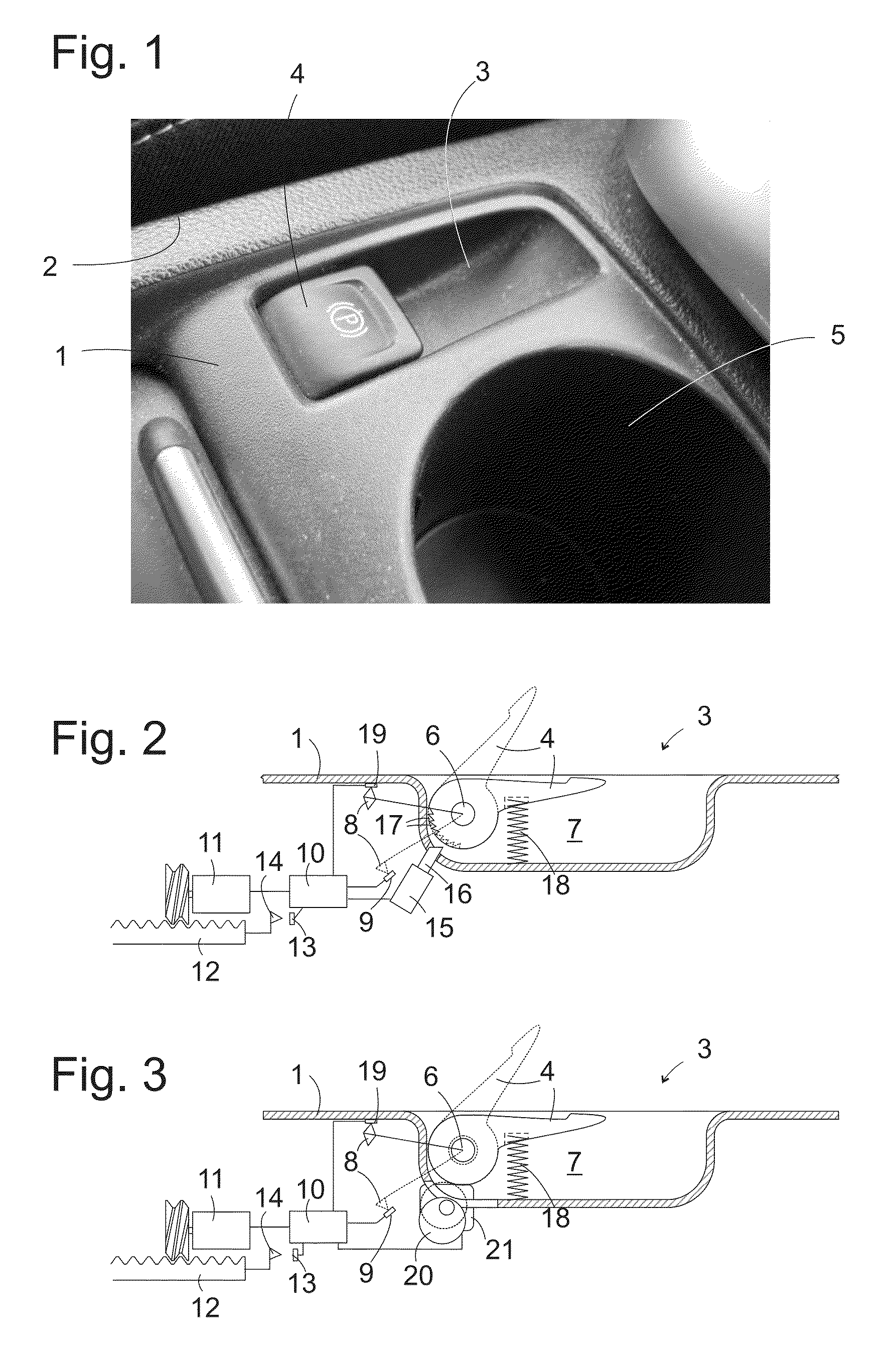
[0022]FIG. 1 shows a perspective view of a cutout from the center console of an automobile. Molded into a plate 1 on the upper side of the center console next to an edge 2 of the latter adjacent to the driver's seat is a trough 3, whose width in the transverse direction of the vehicle is somewhat larger than that of a human finger, e.g., measuring 2 cm, and whose extension in the longitudinal direction corresponds to roughly the length of two finger digits, approx. 5 cm. A lever 4 is pivoted around an axis extending in the transverse direction of the vehicle (not shown on the figure) in a rearward area of the trough 3 relative to the longitudinal direction of the vehicle.

[0...


PUM


Abstract

A hand brake device for a vehicle includes an electric actuator for activating a brake and an operating element that can be moved between a brake position and release position. A control unit triggers the actuator according to the position of the operating element. A locking device for locking the operating element in the brake position is controlled by the control unit.

Description

CROSS REFERENCE TO RELATED APPLICATION[0001]This application claims priority to German Patent Application No. 102013014571.6 filed Sep. 2, 2013 which is incorporated herein by reference in its entirety.TECHNICAL FIELD[0002]The technical field relates to a hand brake device for a vehicle, which encompasses an electric actuator for activating a brake, an operating element that can be moved between a brake position and release position, and a control unit for triggering the actuator according to the position of the operating element.BACKGROUND[0003]Such a hand brake device is known from EP 1 655 190 A1. While the brake is electrically activated in this conventional hand brake device, the operating element resembles the lever in a conventional, purely mechanical hand brake device. The hand brake exhibits a handle to be gripped by the user, and can be locked in a brake position by having a latch engage into a toothed rack. However, while the position of the brake lever in the conventiona...

Claims


Application Information

Patent Timeline
IPC IPC(8): B60T7/10B60T7/08G05G5/06G05G1/04
CPCB60T7/085B60T7/102B60T7/104G05G5/06B60T7/107G05G1/04
Inventor SCHRAMM, THOMASPALASCHINSKI, WINFRIEDLUENENBUERGER, AXELDUCKWITZ, KLAUSHOLL, ANDREAS
Owner GM GLOBAL TECH OPERATIONS LLC
Why Eureka
Try Eureka