Mobile device mounting system and method

Active Publication Date: 2016-04-12
BERNARDS DOUGLAS B
View PDF90 Cites 6 Cited by
  • Summary
  • Abstract
  • Description
  • Claims
  • Application Information

AI Technical Summary

Benefits of technology

[0021]In a preferred embodiment, the mobile device mounting system enables secure recept

Problems solved by technology

Conventional systems may require substantial time and effort for a user to mount a mobile device, such as in the dashboard of a vehicle, on a wall, or at another location.
Other conventional systems may require multiple parts to be engaged and assembled together to hold the mobil

Method used


Image

  • Mobile device mounting system and method
  • Mobile device mounting system and method
  • Mobile device mounting system and method

Examples


first embodiment

A. First Embodiment and Variations

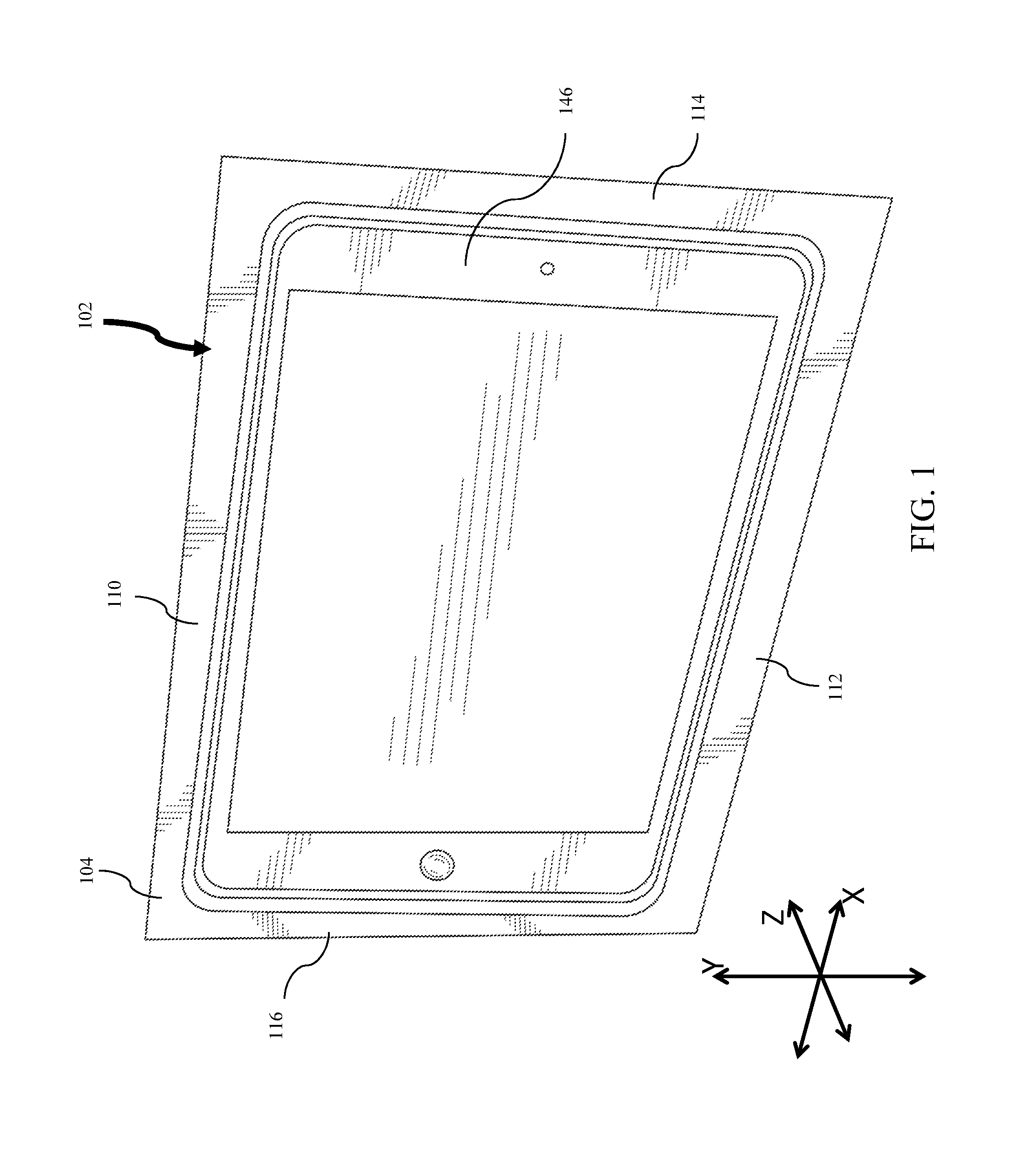
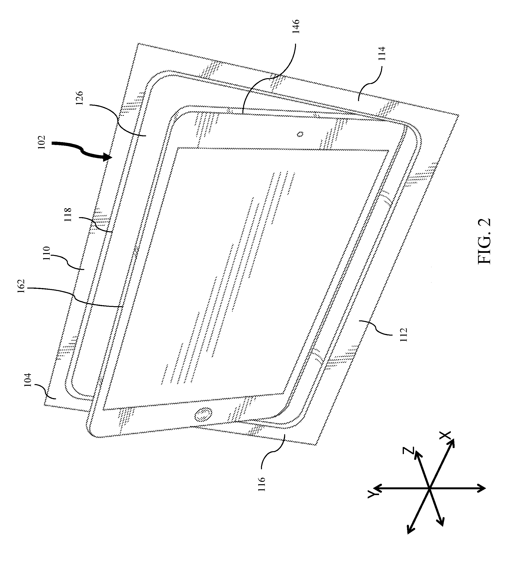
[0039]FIGS. 1, 2, 3, 4, and 5 illustrate features of a mobile device mounting system 102, according to a first embodiment and a variation of the first embodiment. As shown, a Z-axis represents a viewing axis (e.g., a third axis) while the X-axis and the Y-axis (e.g., a first axis and a second axis) represent axes corresponding to a length and width, respectively, of mobile device mounting system 102.

[0040]FIGS. 1 and 2 illustrate a mobile device 146 being held within and being tilted (or rotated) out of the mobile device mounting system 102. In the embodiment of FIG. 1, the mobile device 146 can be held flush within the body of the mobile device mounting system 102, which includes a first end 110, a second 112, a third end 114, and a fourth end 116. Each end includes a flange that extends outward from the center of the mobile device mounting system 102. The flanges may be secured to a fixed object such as a car dash, the back of a seat or headrest, ...

second embodiment

B. Second Embodiment and Variations

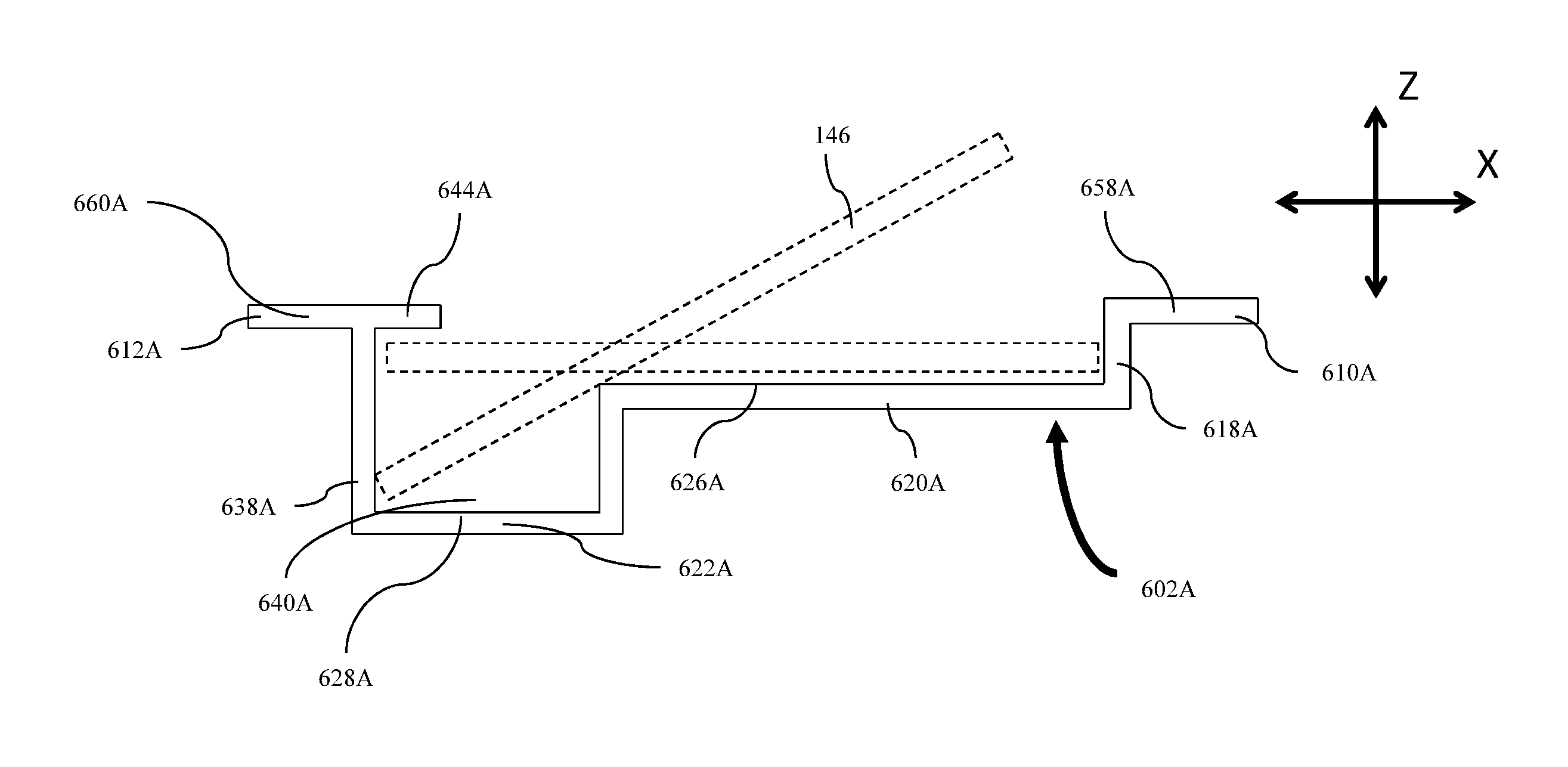
[0050]FIGS. 6 and 7 illustrate features of a mobile device mounting system 102, according to a second embodiment. As shown in FIG. 6, the receiving section 338 is disposed at a side that is adjacent to the first end 310 that includes the magnetic support 318. In this embodiment and its variations, the user may insert the mobile device (e.g. FIG. 1, mobile device 146) into a side adjacent to the magnetic support 318 rather than an opposite end. The second embodiment and its variations may be mounted with the magnetic support 318 at a top, bottom, or lateral edge.

[0051]When the mobile device mounting system 302 is mounted in a car dash and positioned with the magnetic support(s) 318 at a top edge, this may allow the user to more quickly and / or easily insert the mobile device 146 into the mobile device mounting system 302 for users who typically hold a mobile device from a lateral side.

[0052]The system of the second embodiment and its variations may a...


PUM


Abstract

In an embodiment, a mobile device mounting system configured to hold a mobile device having a magnetic edge includes a magnetic support, a rest support, and a receiving section. The rest support is mechanically coupled to the magnetic support and has a first support surface that contacts a first contact surface on a rear side of the mobile device when the mobile device is moved downward to be held by the mobile device mounting system for viewing. The receiving section defines a recessed area configured to receive a part of the mobile device when the mobile device is angled such that the magnetic edge of the mobile device is separated from the magnetic support for user extraction.

Description

CROSS REFERENCE TO RELATED APPLICATION[0001]This application claims the benefit of U.S. Provisional Application Ser. No. 61 / 879,064, filed on Sep. 17, 2013, the entirety of which is incorporated herein by reference.BACKGROUND[0002]1. Technical Field[0003]This invention relates to mounting systems, and more particularly to a mobile device mounting system and method.[0004]2. Description of the Related Art[0005]Conventional systems may require substantial time and effort for a user to mount a mobile device, such as in the dashboard of a vehicle, on a wall, or at another location. For example, a user may be required to use tools to install a cover plate over a mobile device to secure the mobile device in the dashboard. Other conventional systems may require multiple parts to be engaged and assembled together to hold the mobile device in place, which may be difficult for a user to understand and learn how to use. In addition, such conventional systems may involve multiple moving parts, e...

Claims


Application Information

Patent Timeline
IPC IPC(8): A47B91/00F16M11/04
CPCF16M11/041F16M13/00F16M13/02
Inventor BERNARDS, DOUGLAS B.
Owner BERNARDS DOUGLAS B
Why Eureka
Try Eureka