Electric boring tool

a technology of electric boring and electric motor, which is applied in the direction of manufacturing tools, portable power-driven tools, drilling machines, etc., can solve the problem of easy damage in the vicinity of an opening for a hole, and achieve the effect of preventing or easing damag

Inactive Publication Date: 2016-04-19
KOKI HLDG CO LTD
View PDF39 Cites 37 Cited by
  • Summary
  • Abstract
  • Description
  • Claims
  • Application Information

AI Technical Summary

Benefits of technology

[0019]According to the electric boring tool according to the first aspect of the present invention, the motor control unit is capable of automatically exerting control to give low speed rotation (low-speed control) of the electric motor unless load current of the electric motor reaches or exceeds set value after start of operation of the tip tool is detected. It is therefore possible to prevent or ease damage such as splitting and cracking due to drilling while making a hole in work (a workpiece) such as concrete or brick.
[0020]According to the electric boring tool according to the second aspect of the present invention, automatic control at low speed rotation for the electric motor takes place so that vibration or stress occurring at the power transmission mechanism do not reach or exceed set values. The speed of the electric motor is then controlled in response to the extent of pulling of the switch trigger when the vibration or stress occurring in the electric boring tool during automatic control at low speed rotation increase to reach or exceed the set values. It is therefore possible to prevent or ease damage such as splitting and cracking due to drilling while making a hole in work (a workpiece) such as concrete or brick.

Problems solved by technology

However, there is a problem where it is easy for damage to occur in the vicinity of an opening for a hole when creating a hole in brittle work such as concrete or brick.

Method used


Image

  • Electric boring tool
  • Electric boring tool
  • Electric boring tool

Examples


first embodiment

(First Embodiment)

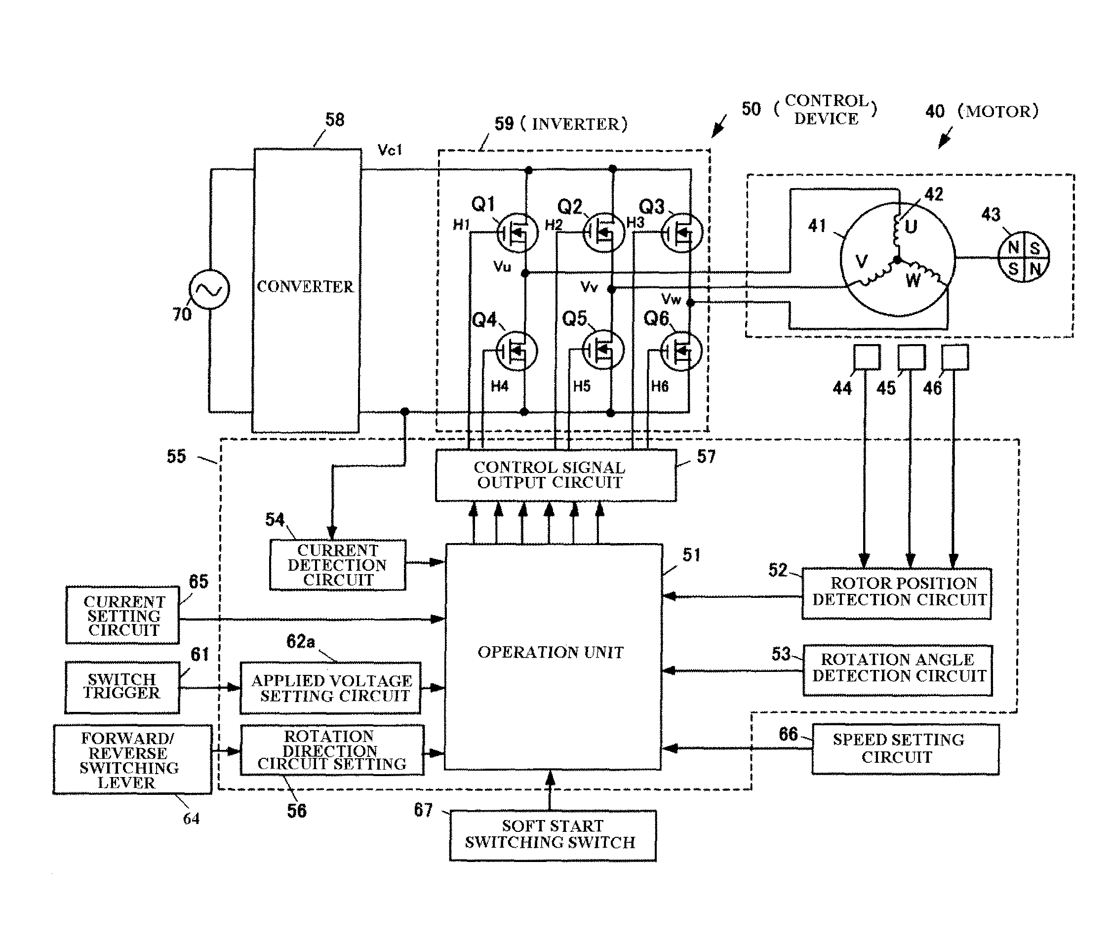
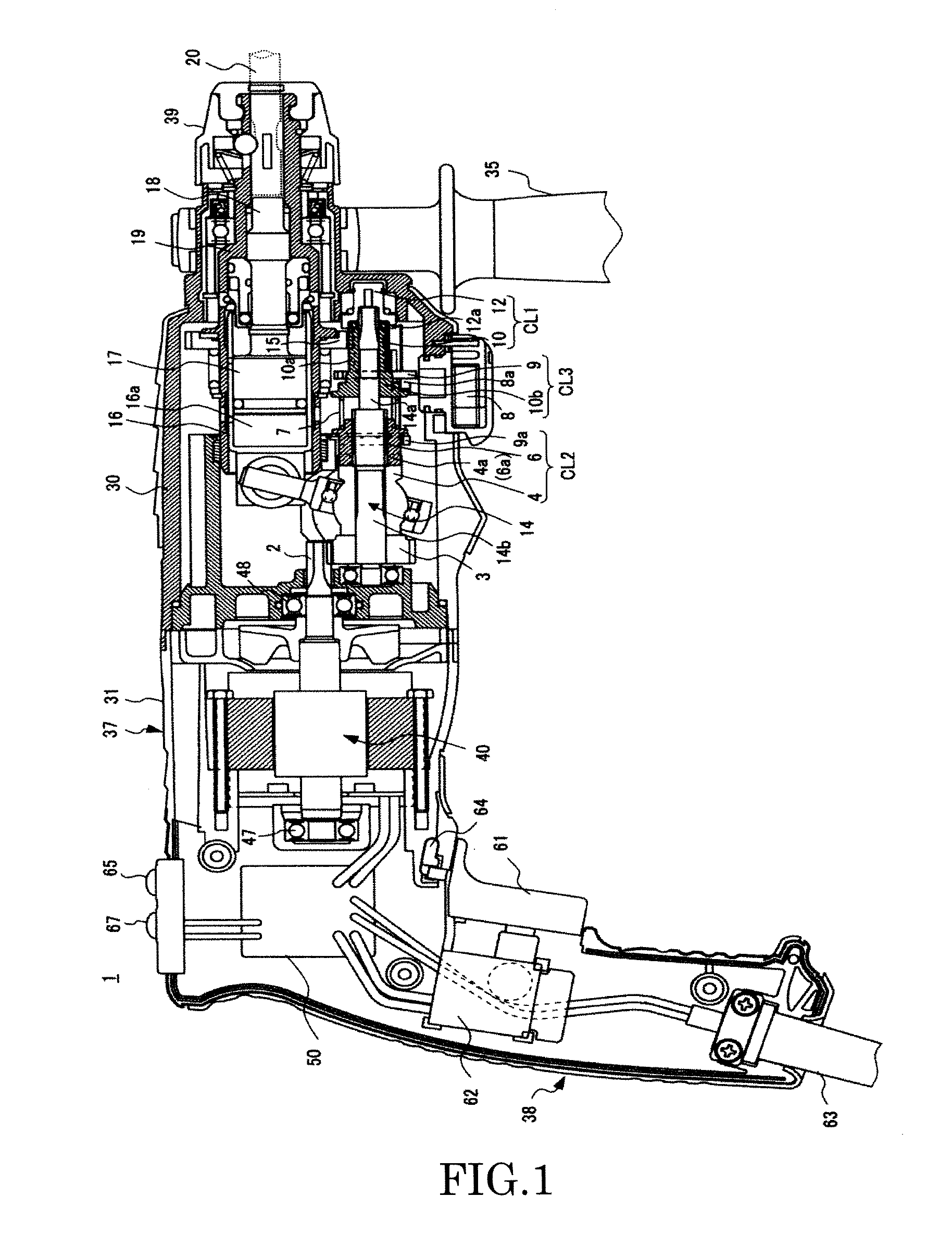
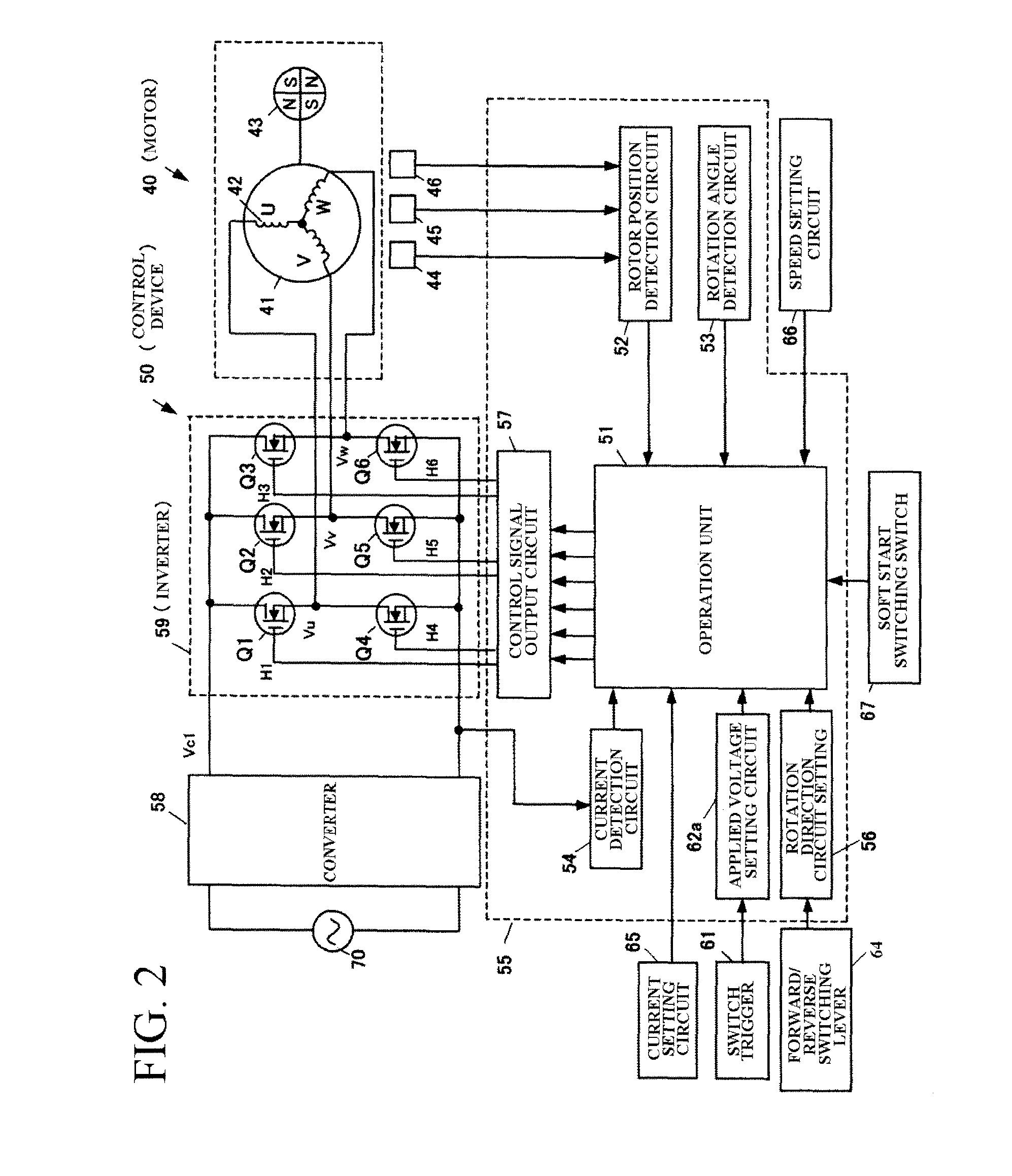
[0032]FIG. 1 is an overall structural view showing the electric boring tool of a first embodiment of the present invention applied to a hammer drill, FIG. 2 is a block diagram of a control device when an electric motor that drives the hammer drill is a brushless motor, and FIG. 3 shows a flowchart of control of the control device for the hammer drill illustrated in FIG. 2.

(Overall Configuration of the Hammer Drill)

[0033]First, an explanation is given of the overall configuration of a hammer drill of the first embodiment of the present invention with reference to FIG. 1 and FIG. 2.

[0034]As illustrated in FIG. 1, a hammer drill 1 includes a tool body comprised of a body housing 37 extending from one end (left end in the drawing) to the other end (right end in the drawing) along the same direction (horizontal axial direction) as an axis of rotation of the brushless motor (DC motor) 40, and a handle housing 38 descending vertically from the body housing 37. A tip tool ...

second embodiment

(Modified Example of Second Embodiment)

[0088]It is possible to use a strain sensor utilizing the characteristics of change in pressure versus change in resistance of a semiconductor element or the like instead of using the acceleration sensor 68 for detecting vibration occurring in the second embodiment. An example illustrated in FIG. 9 illustrates an example where an electric boring tool detects stress (strain) occurring at the intermediate shaft 14 as a result of locating a strain sensor 68a in the vicinity of a bearing of the intermediate shaft 14 constituting the power transmission mechanism. Stress to be detected by the strain sensor may be any stress that occurs in a predetermined position in the power transmission mechanism. Stress occurring in the power transmission mechanism is detected by the strain sensor. It is therefore also possible to obtain the same results as for using the acceleration sensor when the strain sensor is used. Other explanations for the second embodime...


PUM

PropertyMeasurementUnit
electrical anglesaaaaaaaaaa
lengthaaaaaaaaaa
diameter Dsaaaaaaaaaa

Abstract

An electric boring tool comprises an electric motor, a switch trigger, a tip tool driven by driving force of the electric motor, a power transmission mechanism for transmitting the driving force of the electric motor to the tip tool as rotational force and / or hammer force, and a motor control unit for controlling speed of the electric motor in response to an extent of pulling of the switch trigger. The motor control unit subjects the electric motor to low speed control after the electric motor is started up, and controls the speed of the electric motor in response to the extent of pulling of the switch trigger when the load current of the electric motor is set value or greater during the low speed control.

Description

[0001]This application is the U.S. National Phase under 35 U.S.C. §371 of International Application No. PCT / JP2010 / 000581, filed on Feb. 1, 2010, which in turn claims the benefit of Japanese Application No. 2009-021661, filed on Feb. 2, 2009, the disclosures of which Application are incorporated by reference herein.TECHNICAL FIELD[0002]The present invention relates to an electric boring tool such as a hammer drill that drives a bit using an electric motor.BACKGROUND ART[0003]An electric boring tool such as a hammer drill driven by an electric motor is used for forming holes in work material (work) such as concrete and brick by providing rotational force, hammer force or both to a tip tool such as a drill bit using an electric motor. Such an electric boring tool is also used for an operation to trim such a hole. However, there is a problem where it is easy for damage to occur in the vicinity of an opening for a hole when creating a hole in brittle work such as concrete or brick.[0004...

Claims


Application Information

Patent Timeline
Patent Type & Authority Patents(United States)
IPC IPC(8): B25D11/00B25F5/00B23B45/02B25D16/00H02P6/06H02P23/03H02P27/08H02P7/00
CPCB25D16/006H02P6/06H02P23/03H02P27/08B23B45/02B25D2211/061B25D2222/72B25D2250/055B25D2250/095B25D2250/201B25D2250/221B25D2250/255Y02P70/173Y02P70/10
Inventor OOKUBO, TAKAHIROIWATA, KAZUTAKA
Owner KOKI HLDG CO LTD
Why Eureka
Try Eureka