
Rotational force transmitting apparatus

a technology of transmitting apparatus and rotating force, which is applied in the direction of clutches, gearing, clutches, etc., can solve the problems of jolting of the apparatus, etc., and achieve the effect of excellent productivity and thin and small structur

Active Publication Date: 2016-04-19
NAMIKI PRECISION JEWEL CO LTD
View PDF9 Cites 2 Cited by
  • Summary
  • Abstract
  • Description
  • Claims
  • Application Information

AI Technical Summary

Benefits of technology

The present invention is designed to prevent jolting and other instabilities in a mechanical system caused by rotation. It achieves this by using a clutch mechanism to output a rotational force, which prevents instability in the output shaft. The clutch mechanism is located on one side, while a planetary gear mechanism is located on the other side, making the structure thin and small-sized. This invention is also excellent in terms of productivity.

Problems solved by technology

However, those conventional rotational force transmitting apparatuses have jolting (a slightly moving state, not fixed completely as a machine) caused by backlash between gears, a slight gap between a key and an output shaft, or the like.

Method used


Image

  • Rotational force transmitting apparatus
  • Rotational force transmitting apparatus
  • Rotational force transmitting apparatus

Examples


example

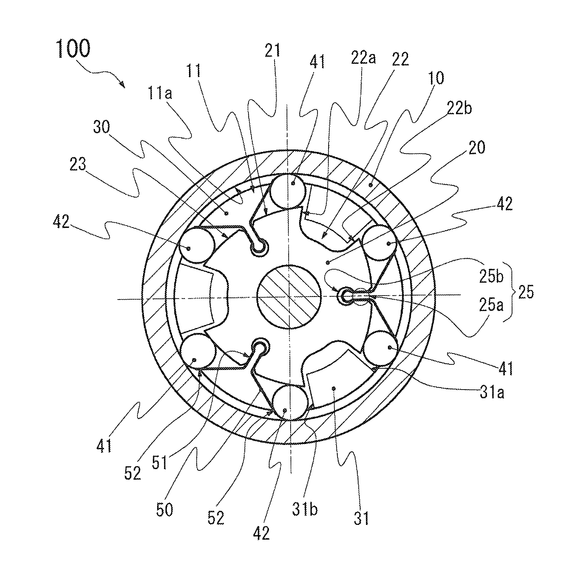
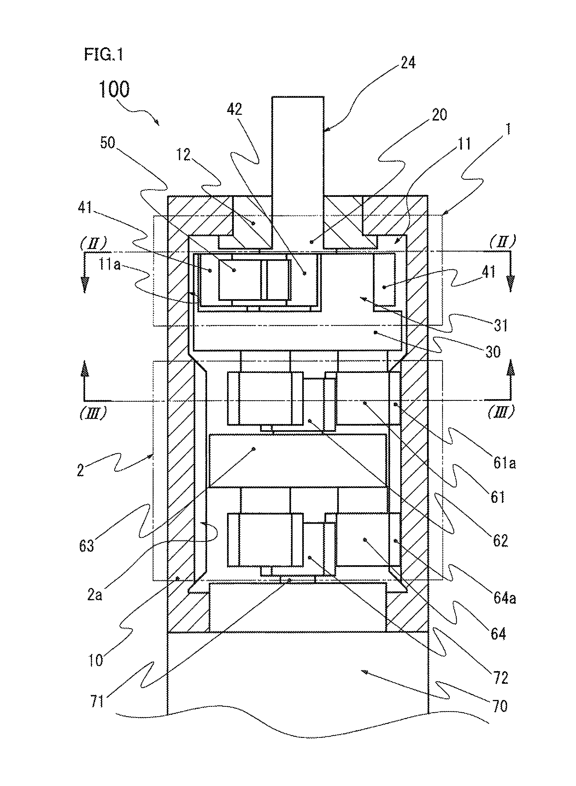
[0027]FIG. 1 is a longitudinal sectional view illustrating an internal structure of a rotational force transmitting apparatus 100 in this example. This longitudinal sectional view shows only a fixing member 10 housing a mechanism section and an output-side support member 12.

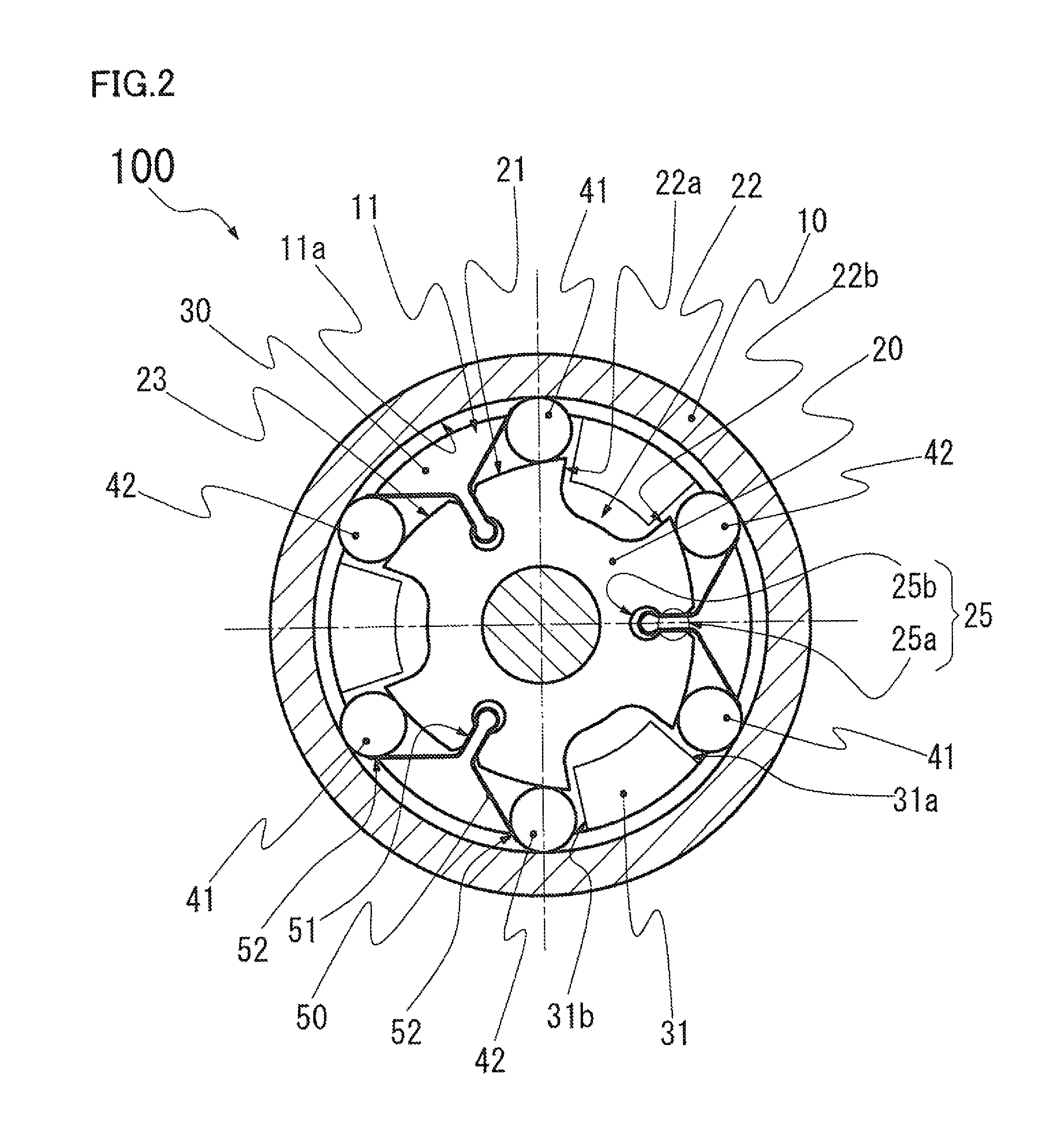
[0028]In the rotational force transmitting apparatus 100, as illustrated in FIG. 1, a clutch mechanism 1 and a planetary gear mechanism 2 are coupled to each other in an axial direction in the fixing member 10. The rotational force transmitting apparatus 100 is configured so that a rotational force inputted to a sun gear 62 of the planetary gear mechanism 2 is outputted from an output rotation member 20 of the clutch mechanism 1.

[0029]The fixing member 10 having a tubular shape has an inner circumferential surface having a substantially columnar shape. The fixing member 10 includes a housing chamber 11 having an inner circumferential surface 11a on one side (upper side in FIG. 1) in an axial direction thereof and...


PUM


Abstract

Provided is a rotational force transmitting apparatus that can prevent jolting of an output shaft in a circumferential direction caused by jolting in an input-side mechanism in the circumferential direction, has a thin and small structure, and is excellent in productivity. In the rotational force transmitting apparatus, a clutch mechanism 1 and a planetary gear mechanism 2 are axially coupled in a fixing member 10, and a rotational force inputted to a sun gear 62 of the planetary gear mechanism 2 is outputted from an output rotation member 20 of the clutch mechanism 1. On the fixing member 10, a substantially columnar inner-circumferential surface is provided. A housing chamber 11 housing the clutch mechanism 1 is constituted by the inner circumferential surface on one side in an axial direction. An internal gear 2a of the planetary gear mechanism 2 engaging with planetary gears 61 is provided on the other side.

Description

TECHNICAL FIELD[0001]The present invention relates to a rotational force transmitting apparatus for adjusting an input-side rotation to appropriate number of rotations and appropriate torque and outputting the input-side rotation.BACKGROUND ART[0002]Examples of the conventional rotational force transmitting apparatuses include a rotational force transmitting apparatus in which rotation of an input-side gear is transmitted to an output-side gear via multi-stages of gears and a rotational force transmitting apparatus in which a rotation shaft of a motor or a rotation shaft of another gear is connected to an output shaft via a rotation transmitting member such as a key and a spline.[0003]However, those conventional rotational force transmitting apparatuses have jolting (a slightly moving state, not fixed completely as a machine) caused by backlash between gears, a slight gap between a key and an output shaft, or the like. The conventional rotational force transmitting apparatuses furth...

Claims


Application Information

Patent Timeline
Patent Type & Authority Patents(United States)
IPC IPC(8): F16D41/10F16H1/28F16H1/46F16D43/02
CPCF16H1/2863F16D41/105F16D43/02F16H1/46
Inventor KOBAYASHI, YASUYUKIODAGIRI, KINYA
Owner NAMIKI PRECISION JEWEL CO LTD
Learn More