
Portable terminal

a terminal and portability technology, applied in the field of portability terminals, can solve the problems of damage to the board-side connecting portion and the battery-side connecting portion, and the battery pack cannot follow the circuit board that moves with respect to the casing, and achieve the effect of ensuring the connection of the battery pack to the circuit board

Active Publication Date: 2016-04-19
PANASONIC INTELLECTUAL PROPERTY MANAGEMENT CO LTD
View PDF34 Cites 17 Cited by
  • Summary
  • Abstract
  • Description
  • Claims
  • Application Information

AI Technical Summary

Benefits of technology

[0009]Moreover, the restraining member restrains the movement of the battery pack with respect to the circuit board in the surface direction of the circuit board is restrained by. Thus, the relative positions of the circuit board and the battery pack can be maintained. Consequently, the board-side connecting portion and the battery-side connecting portion are not damaged, and instantaneous disconnection therebetween is not caused. Accordingly, the connection of the battery pack to the circuit board can be assured.
[0011]The circuit board and the restraining member can be formed integrally with each other via the chassis by fixing the restraining member to the chassis which holds the circuit board. Consequently, if an impact of the fall or the like of the portable terminal is applied thereto, the battery pack can be made to follow the circuit board attached in a floating state to the casing. Thus the relative positions of the circuit board and the battery packs can reliably be maintained.
[0013]The tip end of one of the board fixing screw and the restraining member fixing screw does not contact the display device. Consequently, the display device is not damaged by the board fixing screw or the restraining member fixing screw. In addition, the thickness of the portable terminal can be reduced.
[0019]Moreover, the shape of the chassis buffer member can be minimized by providing the chassis buffer member only at a plane angle portion of the chassis.
[0024]Here, the board-side connecting portion is connected to the circuit board via the wiring member. The wiring member is a deformable member. Consequently, the movement of the circuit board is absorbed by the deformation of the wiring member Accordingly, a state of connecting the board-side connecting portion to the battery-side connecting portion can be maintained.
[0031]According to the aspects of the present invention, the circuit board is fixed to be movable within a given range in a surface direction of the circuit board. Consequently, the circuit board is not damaged due to an impact of the fall or the like of the portable terminal. Moreover, movement of a battery pack is restrained by a restraining member, whereby relative positions of the circuit board and the battery pack can be maintained. Consequently, damage on and instantaneous disconnection between a board-side connecting portion and a battery-side connecting portion do not occur. Accordingly, the connection of the battery pack to the circuit board can be assured.

Problems solved by technology

However, if the circuit board is attached in the floating state to the casing in the portable terminal, the battery pack cannot follow the circuit board that moves with respect to the casing when an impact is applied to the portable terminal.
Thus, damage on the board-side connecting portion and the battery-side connecting portion, and instantaneous disconnection therebetween may occur.

Method used


Image

  • Portable terminal
  • Portable terminal
  • Portable terminal

Examples


first embodiment

[0086](First Embodiment)

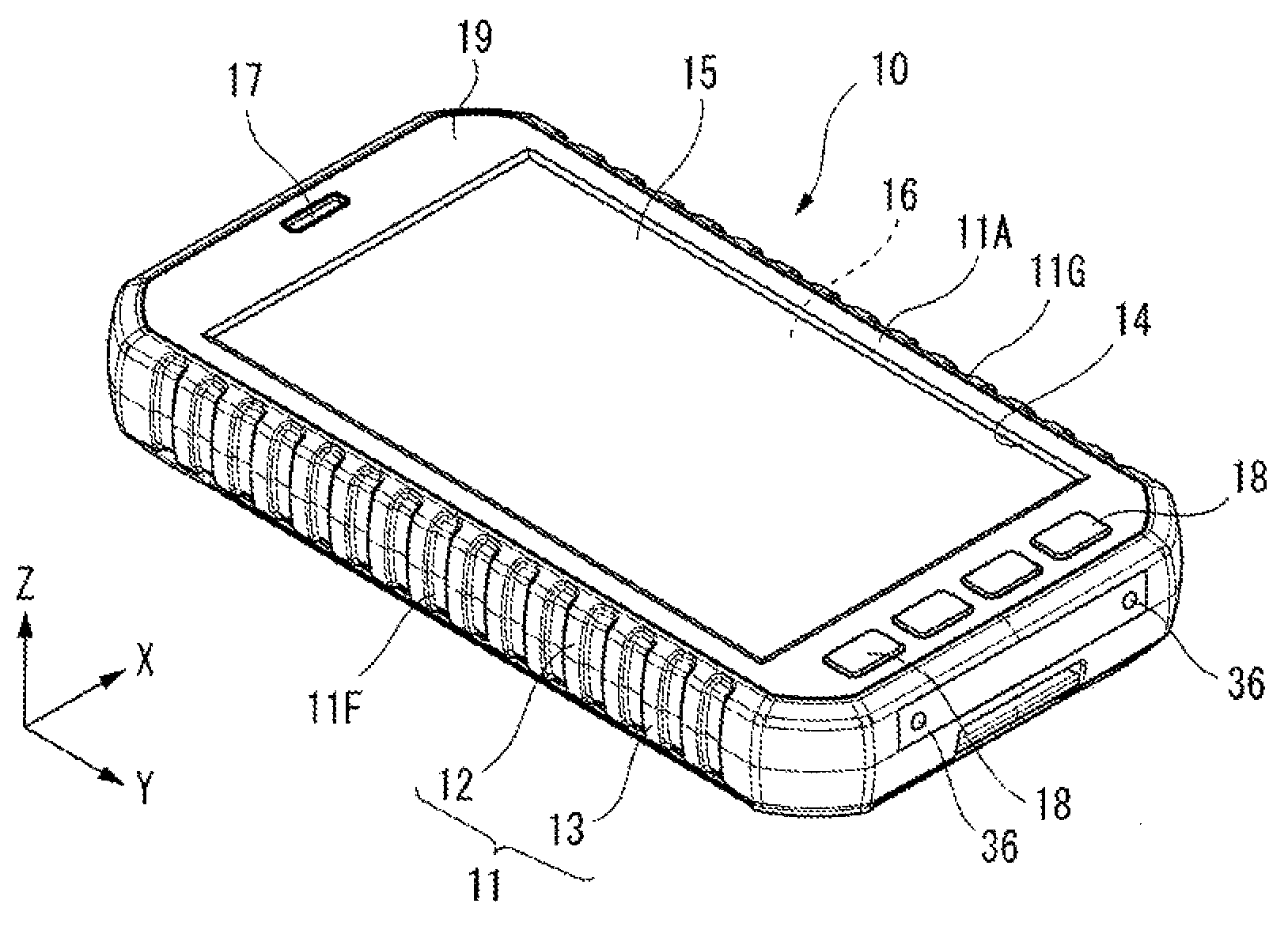
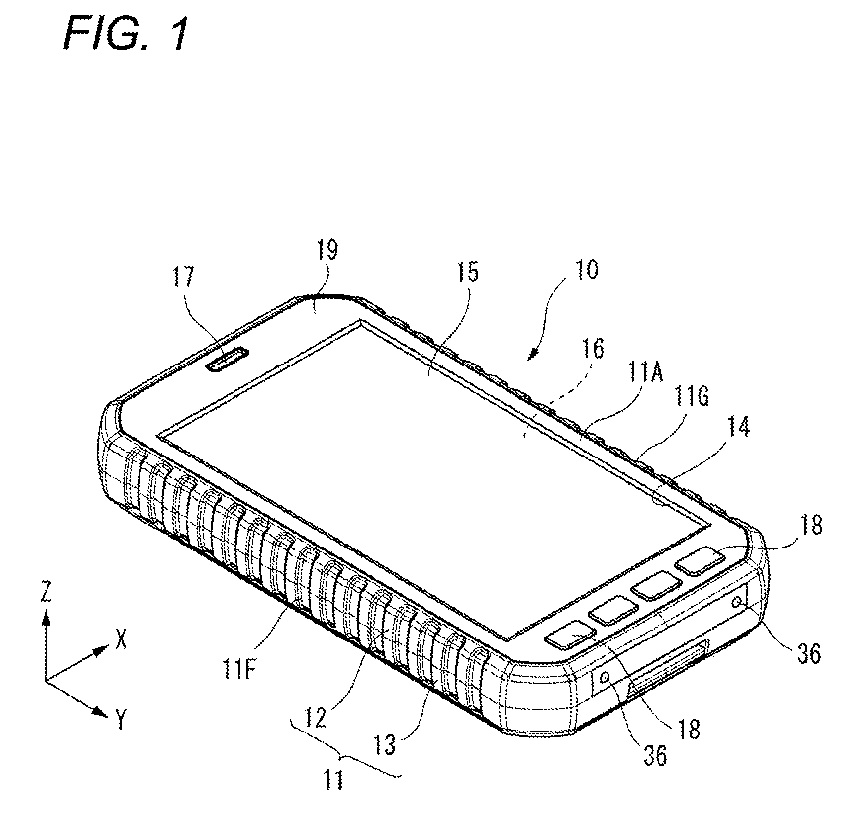
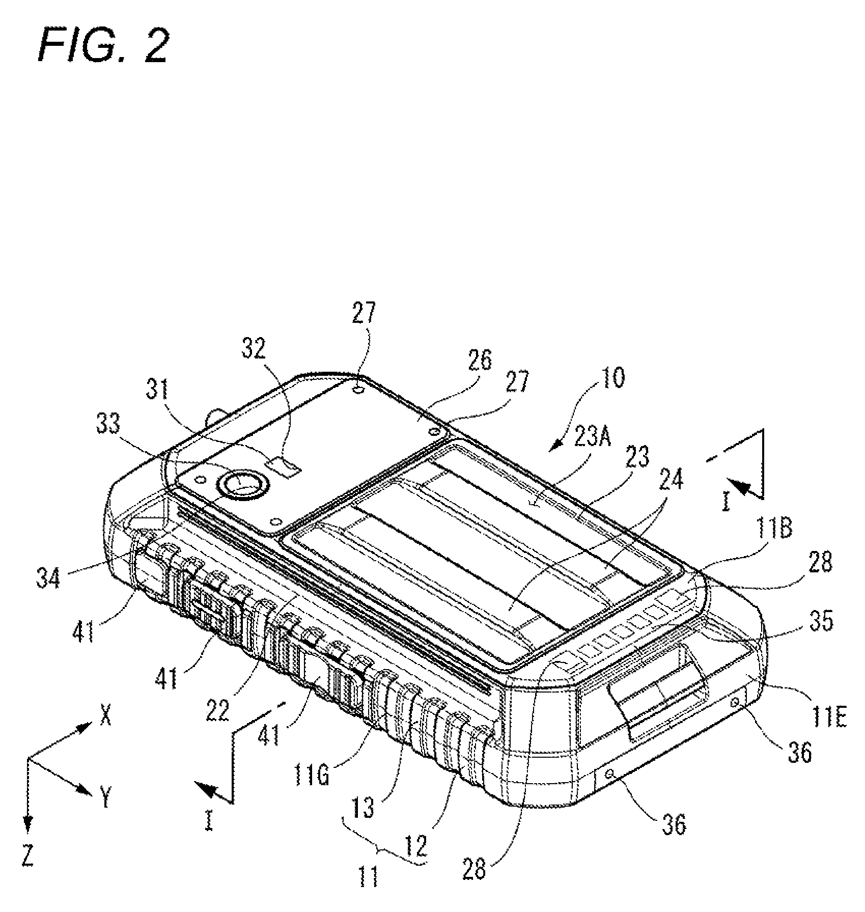
[0087]As illustrated in FIGS. 1 and 2, a portable terminal 10 includes the casing 11 formed substantially like a rectangular parallelepiped, to which a front case 12 and a rear case 13 are assembled.

[0088]A side-part of the casing 11, which corresponds to the front surface 11A is configured by the front case 12. The other side-part of the casing 11 which corresponds to the rear surface 11B, is configured by the rear case 13.

[0089]A substantially-rectangular frame member 19 is provided on the front surface 11A of the casing 11. An opening portion 14 is formed by the frame member 19. The opening portion 14 is covered with an operating panel 15. A display device 16 is incorporated in the casing 11 is covered by the operating panel 15. Moreover, a receiver tone-hole 17 is formed in a part of the front surface 11A of the casing 11, which part is at an upper side of the operating panel 15. An operating key 18 is provided in the neighborhood of the operating panel 1...

modification 1

[0108](Modification 1)

[0109]Modification 1 of the fixing portion 53 is described hereinafter with reference to FIG. 9.

[0110]A fixing portion 81 according to Modification 1 includes a fixing buffer member 82 for holding the circuit board 52 in the chassis 51, a collar 83 provided in a fixing buffer member 82, and board fixing screw 73 for fixing the circuit board 52 to the chassis 51. The fixing buffer member 82 is provided on the outer periphery of the collar 83. A lower concave portion 82A is formed on a lower part of the fixing buffer member 82, an upper concave portion 82B is formed on an upper part of the fixing buffer member 82.

[0111]A protrusion portion 83A of the collar 83 is arranged on the upper concave portion 82B. The circuit board 52 is arranged on the lower concave portion 82A. The board fixing screw 73 inserted into the collar 83 is screwed into the screw hole 51D of the chassis 51. Thus the circuit board 52 is fixed to the chassis 51 with the board fixing screw 73 via...

modification 2

[0114](Modification 2)

[0115]Modification 2 of the fixing portion 53 is described hereinafter with reference to FIG. 10.

[0116]A fixing portion 151 according to Modification 2 includes a board fixing screw 152 for fixing the circuit board 52 to the chassis 51 by rigid fixation, a fixing buffer member 153 for fixing the chassis 51 by floating fixation, a collar 154 and a chassis fixing screw 155. The circuit board 52 is fixed to the chassis 51 with the board fixing screw 152 together with the battery housing portion 54.

[0117]The chassis 51 is fixed to the casing 11 by floating fixation with the chassis fixing screw 155 via the fixing buffer member 153 and the collar 154.

[0118]The chassis 51 is fixed with the fixing buffer member 153 by floating fixation. Thus, an impact applied to the circuit board 52 can be alleviated by the fixing buffer member 153. Moreover, the chassis fixing screws 155 are made to respectively penetrate through the fixing buffer members 153. Thus, if a horizontal ...


PUM


Abstract

A portable terminal includes: a casing; a circuit board; a display device; and a fixing portion which fixes the circuit board to the casing to allow the circuit board to move within a given range along a surface direction of the circuit board. The portable terminal further includes: a battery housing portion provided at a position in the casing located along a thickness direction of the circuit board; a battery pack housed in the battery housing portion through a battery opening provided in the casing; a board-side connecting portion provided at the circuit board; a battery-side connecting portion provided at the battery pack and connected to the board-side connecting portion; and a restraining member which restrains a movement of the battery pack with respect to the circuit board along a surface direction of the circuit board.

Description

BACKGROUND[0001]1. Technical Field[0002]The present invention relates to a portable terminal in which a battery pack is housed in a battery housing portion, thereby connecting a battery-side connecting portion of the battery pack to a board-side connecting portion of a circuit board.[0003]2. Description of Related Art[0004]In a portable terminal, a circuit board is fixed in a casing, and a battery pack is housed in a battery housing concave portion of the casing, whereby a battery-side connecting portion of the battery pack is connected to a board-side connecting portion of the circuit board. The battery pack housed in the battery housing concave portion is covered with a lid body. The battery pack is housed in the battery housing concave portion, thereby being retained while fixed in the battery housing concave portion (see JP-A-2000-349875, paragraph 0013 and FIG. 2).SUMMARY[0005]In recent years, in order to prevent breakage of the circuit board, it has been proposed that the circ...

Claims


Application Information

Patent Timeline
Patent Type & Authority Patents(United States)
IPC IPC(8): H05K5/00G06F1/16H04M1/02H04M1/18H04M1/21H04M1/725
CPCG06F1/1626G06F1/1632G06F1/1635G06F1/1639G06F1/1658H04M1/0262H04M1/0277H04M1/185H04M1/21H04M1/72527H04M2250/54H04M1/724092
Inventor MOCHIZUKI, KENICHIWAKIYAMA, YASUJI
Owner PANASONIC INTELLECTUAL PROPERTY MANAGEMENT CO LTD
Learn More