
Portable terminal

Active Publication Date: 2014-08-14
PANASONIC INTELLECTUAL PROPERTY MANAGEMENT CO LTD
View PDF17 Cites 5 Cited by
  • Summary
  • Abstract
  • Description
  • Claims
  • Application Information

AI Technical Summary

Benefits of technology

This patent describes a portable terminal that includes a circuit board and battery pack connected together through a flexible wiring member. A restraining member is used to prevent movement of the battery pack in the surface direction of the circuit board, which helps maintain the relative positions of the two components and prevents damage to the connection between them. This ensures a reliable and secure connection between the battery pack and circuit board, even in the event of an impact. The design also prevents damage to the display device and reduces the thickness of the portable terminal.

Problems solved by technology

However, if the circuit board is attached in the floating state to the casing in the portable terminal, the battery pack cannot follow the circuit board that moves with respect to the casing when an impact is applied to the portable terminal.
Thus, damage on the board-side connecting portion and the battery-side connecting portion, and instantaneous disconnection therebetween may occur.

Method used


Image

  • Portable terminal
  • Portable terminal
  • Portable terminal

Examples


first embodiment

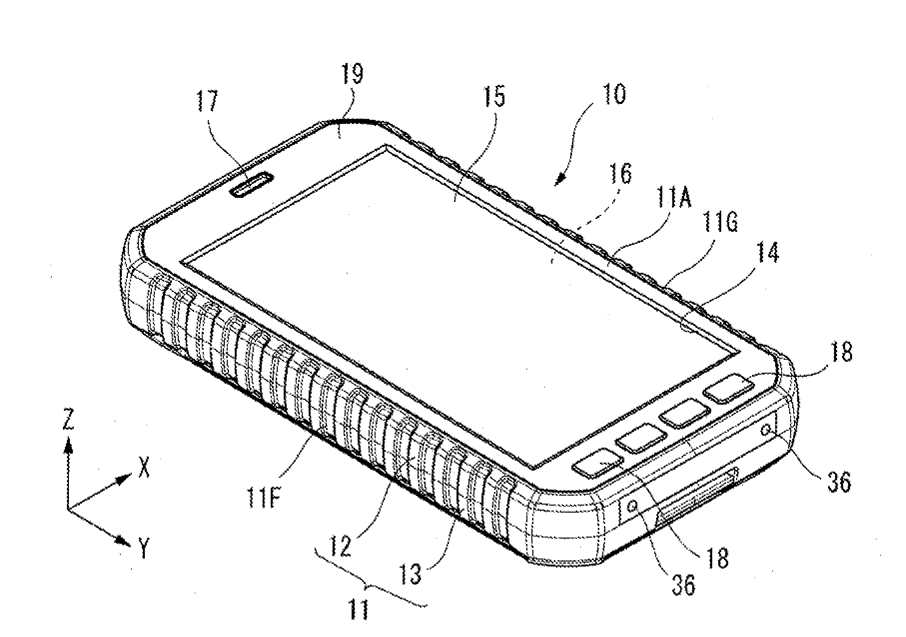
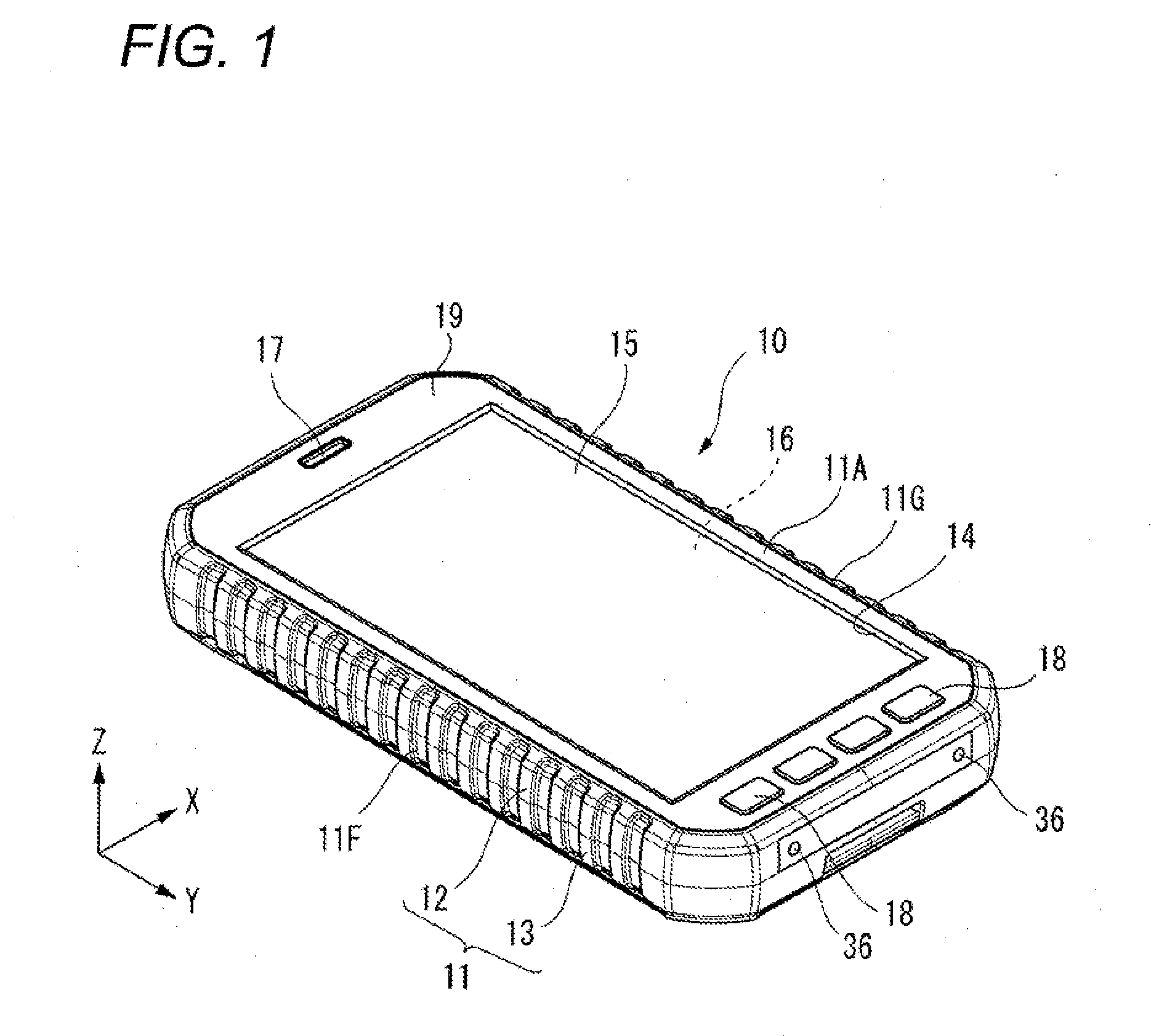
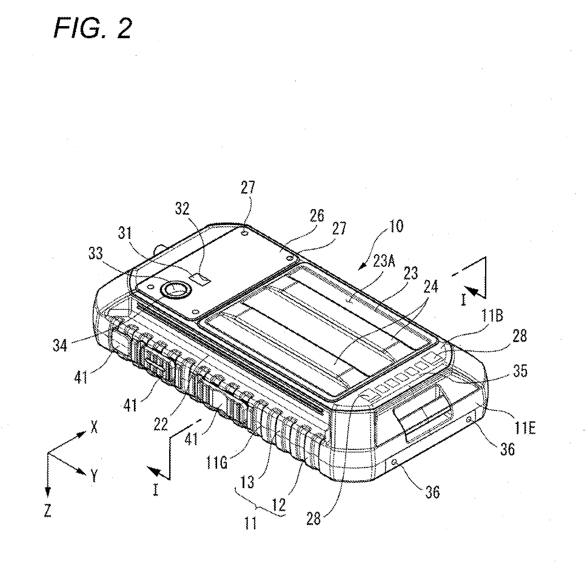
[0086]As illustrated in FIGS. 1 and 2, a portable terminal 10 includes the casing 11 formed substantially like a rectangular parallelepiped, to which a front case 12 and a rear case 13 are assembled.

[0087]A side-part of the casing 11, which corresponds to the front surface 11A is configured by the front case 12. The other side-part of the casing 11 which corresponds to the rear surface 11B, is configured by the rear case 13.

[0088]A substantially-rectangular frame member 19 is provided on the front surface 11A of the casing 11. An opening portion 14 is formed by the frame member 19. The opening portion 14 is covered with an operating panel 15. A display device 16 is incorporated in the casing 11 is covered by the operating panel 15. Moreover, a receiver tone-hole 17 is formed in a part of the front surface 11A of the casing 11, which part is at an upper side of the operating panel 15. An operating key 18 is provided in the neighborhood of the operating panel 15.

[0089]As illustrated i...

second embodiment

[0157]As illustrated in FIG. 47, a portable terminal 160 according to the second embodiment includes a chassis 162 configured to be movable to the casing 11, a circuit board 163 supported by the chassis 162, and a board-side connecting portion 166 connected to the circuit board 163 via a wiring member 164.

[0158]The chassis 162 is housed in the casing 11 and supposed to be movable with respect to the casing 11. The circuit board 163 in a state of being supported by the chassis 162 is housed in the casing 11 and arranged to be movable with respect to the casing 11. Thus, if the circuit board 163 is moved by an impact, the circuit board 163 can be protected by the chassis 162 by supporting the circuit board 163 in the chassis 162.

[0159]As illustrated in FIG. 48, the board-side connecting portion 166 is connected to the circuit board 163 via the wiring member 164. A flexible (i.e., elastically deformable) printed board or a cable through which an electrical signal passes is used as the ...


PUM


Abstract

A portable terminal includes: a casing; a circuit board; a display device; and a fixing portion which fixes the circuit board to the casing to allow the circuit board to move within a given range along a surface direction of the circuit board. The portable terminal further includes: a battery housing portion provided at a position in the casing located along a thickness direction of the circuit board; a battery pack housed in the battery housing portion through a battery opening provided in the casing; a board-side connecting portion provided at the circuit board; a battery-side connecting portion provided at the battery pack and connected to the board-side connecting portion; and a restraining member which restrains a movement of the battery pack with respect to the circuit board along a surface direction of the circuit board.

Description

BACKGROUND[0001]1. Technical Field[0002]The present invention relates to a portable terminal in which a battery pack is housed in a battery housing portion, thereby connecting a battery-side connecting portion of the battery pack to a board-side connecting portion of a circuit board.[0003]2. Description of Related Art[0004]In a portable terminal, a circuit board is fixed in a casing, and a battery pack is housed in a battery housing concave portion of the casing, whereby a battery-side connecting portion of the battery pack is connected to a board-side connecting portion of the circuit board. The battery pack housed in the battery housing concave portion is covered with a lid body. The battery pack is housed in the battery housing concave portion, thereby being retained while fixed in the battery housing concave portion (see JP-A-2000-349875, paragraph 0013 and FIG. 2).SUMMARY[0005]In recent years, in order to prevent breakage of the circuit board, it has been proposed that the circ...

Claims


Application Information

Patent Timeline
IPC IPC(8): H05K5/00
CPCH05K5/0086G06F1/1632G06F1/1635G06F1/1639G06F1/1658H04M1/0262H04M1/0277H04M1/185H04M1/21H04M2250/54G06F1/1626H04M1/724092
Inventor MOCHIZUKI, KENICHIWAKIYAMA, YASUJI
Owner PANASONIC INTELLECTUAL PROPERTY MANAGEMENT CO LTD
Learn More