Ventilation unit for flow reversal

a technology of flow reversal and ventilation unit, which is applied in ventilation systems, lighting and heating apparatus, heating types, etc. it can solve the problems of inconvenient operation, inconvenient maintenance, and high system cost, and achieves a linear and turbulence-free gas flow. , the effect of reducing the turbulence of the gas flow

Active Publication Date: 2016-04-26
ENTSORGAFIN
View PDF19 Cites 3 Cited by
  • Summary
  • Abstract
  • Description
  • Claims
  • Application Information

AI Technical Summary

Benefits of technology

[0022]Thanks to the presence of a simple wing provided along the piping arrangement, the turbulence of the gas flow is reduced and, consequently, also head losses are lower.
[0023]In particular, by realizing the switching devices as simple wings, the size of the clearance of the connections between the delivery and suction ducts and said first piping arrangement at these wings can be maximized, which facilitates a linear and turbulence-free behavior of the gas flow.
[0024]Owing to the fact that the only moving mechanical parts in the ventilation unit according to the invention are the aforementioned switching devices and that said switching devices are housed in a single switching assembly and are driven by a single common actuator, said ventilation unit is reliable and resistant and has very limited manufacturing and operating costs.

Problems solved by technology

A drawback of the last described solution lies in its structural and operational complexity and, consequently, in its requiring a non-negligible expenditure of resources; indeed, it is necessary to set up a quite articulated circuit, in which each valve requires its own actuator, this making the system extremely expensive.
Even if the ventilation unit described in EP 2 017 481 constitutes a satisfactory solution for effecting flow reversal of a gas flow generated by a fan without reversing the rotation direction of the fan, it is not free from drawbacks.
However, also the ventilation unit described in the aforesaid document has a complex structure with a high number of moving parts, which involves a remarkable risk of failures and malfunctioning, thus making the reliability of the ventilation unit unsatisfactory.
The document U.S. Pat. No. 4,310,020 too describes a ventilation unit that is very complex and has a high number of moving part and it is therefore scarcely reliable.
However, the ventilation unit described therein allows only to reverse the flow along a closed-loop flow circuit, but it does not allow, for instance, to suck fresh air from the outside, this remarkably limiting the field of its possible applications and making it unsuitable, inter alia, for applications in plants for the aerobic treatment of organic waste.

Method used


Image

  • Ventilation unit for flow reversal
  • Ventilation unit for flow reversal
  • Ventilation unit for flow reversal

Examples


Embodiment Construction

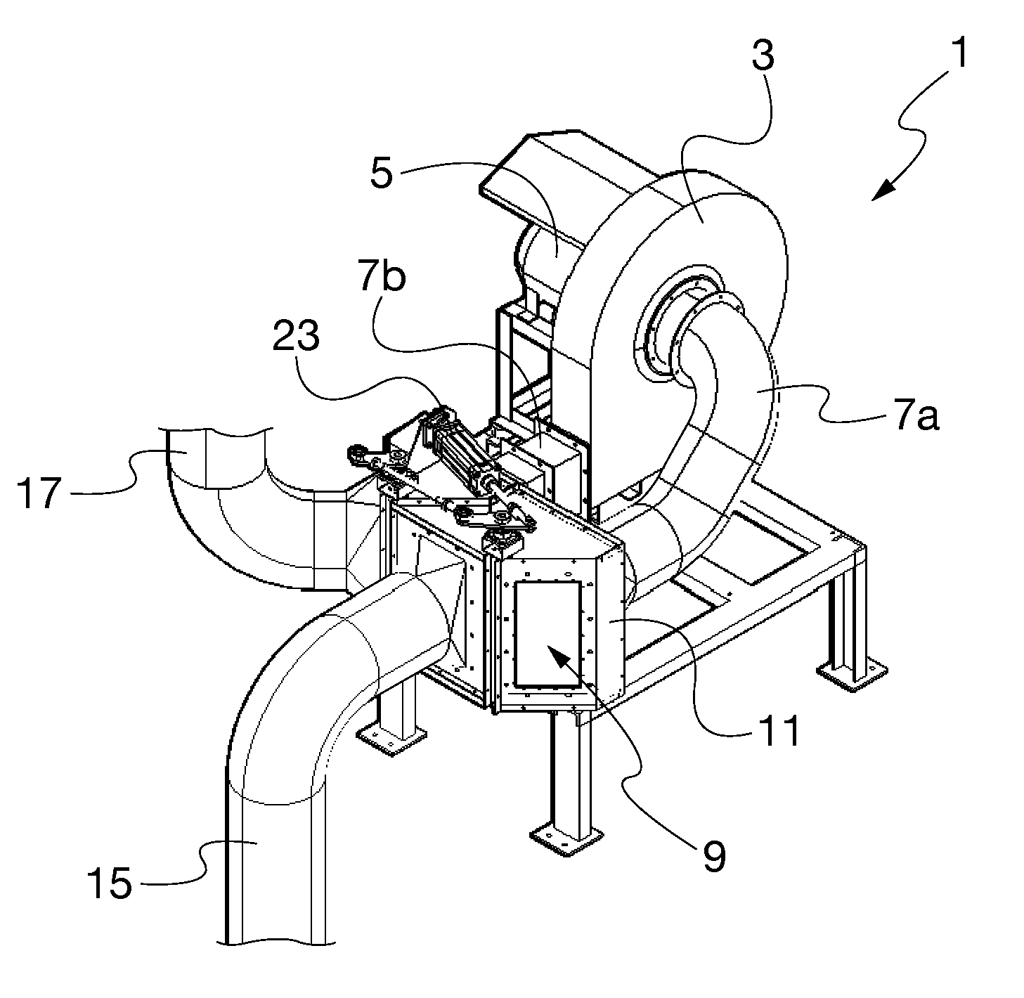
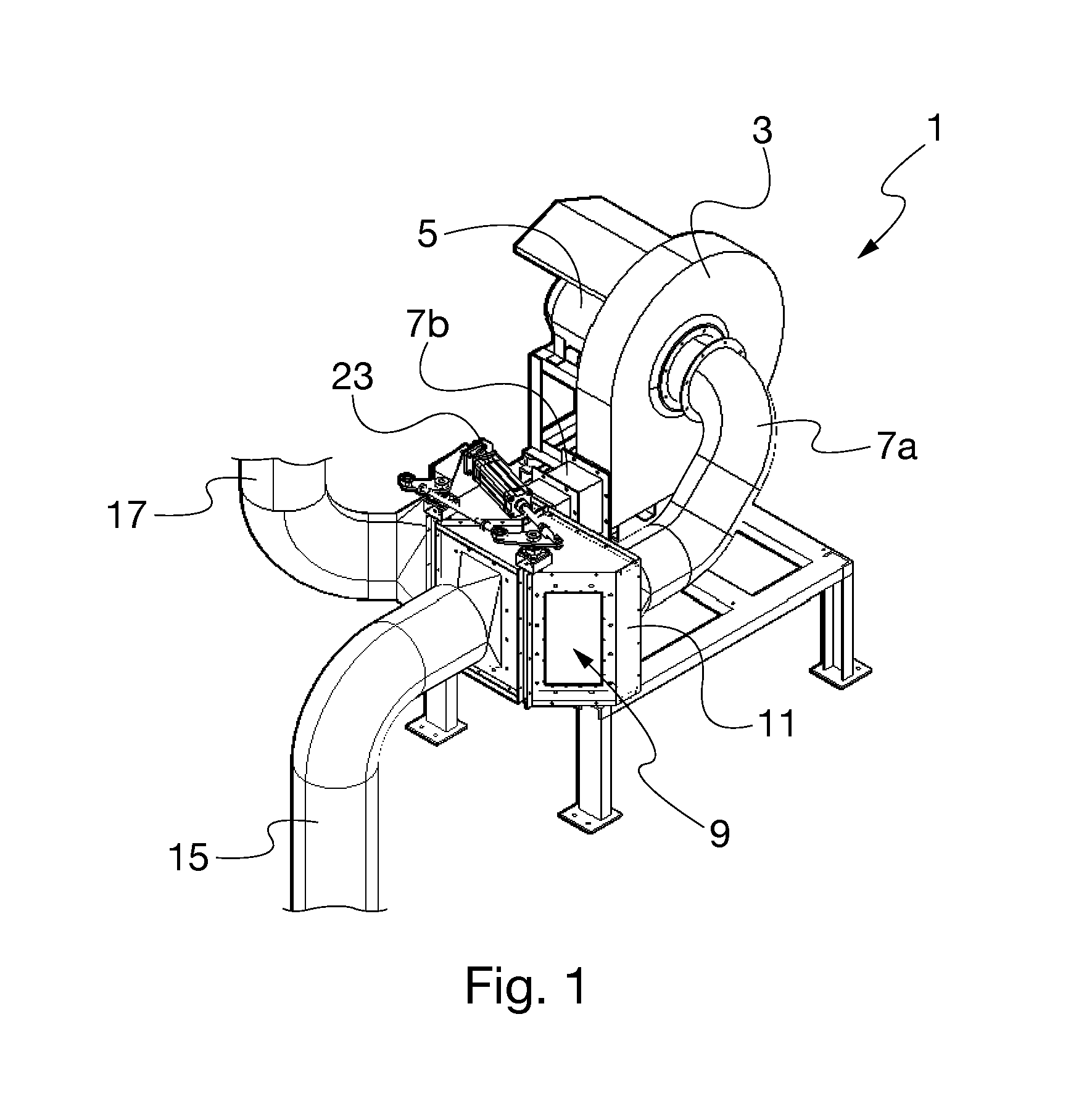
[0031]With reference to FIG. 1, the ventilation unit 1 according to the invention comprises a suitably shaped housing 3, to be connected to a fan 5 having the function of moving the air flow to be processed, by conferring it the desired flow rate, prevalence and direction.

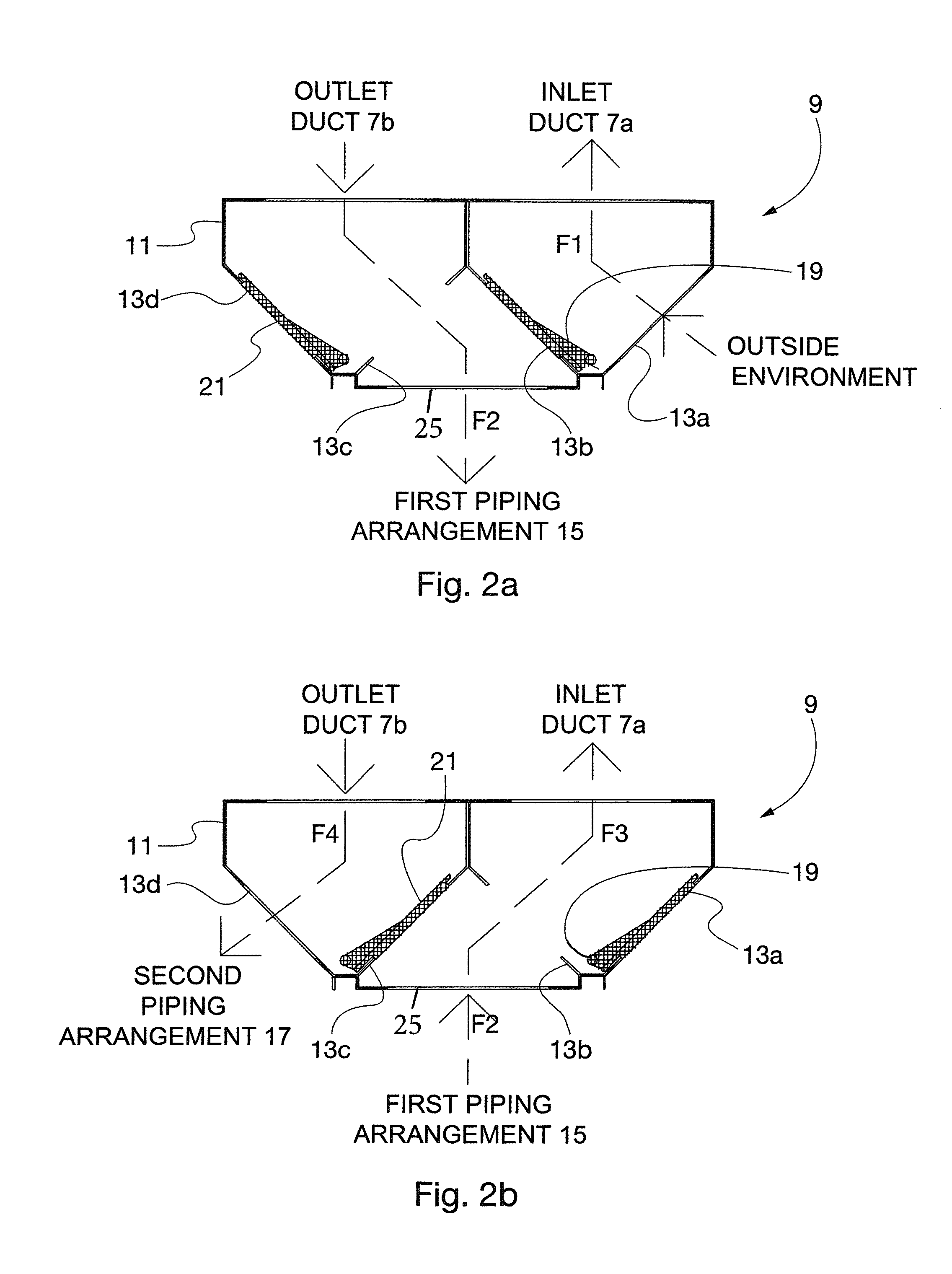
[0032]The housing 3 is connected through a first duct or suction duct 7a and through a second duct or delivery duct 7b to a switching assembly 9, and more particularly to the casing 11 of said switching assembly 9.

[0033]With reference also to FIGS. 2a and 2b, according to the invention in said casing 11 of the switching assembly 9, in addition to the passages at the suction duct 7a and delivery duct 7b, and in addition to a passage at a fifth opening (25) at a first piping arrangement there are provided four additional openings 13a,13b,13c,13d of which a first opening 13a connects the casing 11 to the outer environment, a second opening 13b and a third opening 13c connect the casing 11 to the fifth opening (25) at ...


PUM

PropertyMeasurementUnit
suctionaaaaaaaaaa
sizeaaaaaaaaaa
flow rateaaaaaaaaaa

Abstract

A ventilation unit is arranged to effect flow reversal, according to two opposite directions, of a gas flow generated by a fan without reversing the rotation direction of the fan. The ventilation unit includes a fan, at least a first piping arrangement through which a gas flow is intended to pass in one of the two possible directions depending on whether it is blown or sucked by the fan, and a switching assembly arranged between the fan and the at least a first piping arrangement, at least a pair of switching devices being provided in the switching assembly and being movable between two positions for selectively and alternately connecting the at least a first piping arrangement to a delivery duct and to a suction duct of the fan, so as to allow the passage of a gas flow in a direction or in the opposite direction within the at least a first piping arrangement.

Description

TECHNICAL FIELD OF THE INVENTION[0001]The present invention refers to a ventilation unit arranged to effect flow reversal, according to two opposite directions, of a gas flow.[0002]More precisely, the present invention refers to a ventilation unit arranged to effect flow reversal, according to two opposite directions, of a gas flow generated by a fan without reversing the rotation direction of the fan.[0003]Particularly, the present invention refers to a ventilation unit arranged to effect flow reversal, according to two opposite directions, of a gas flow applicable to plants for the aerobic treatment of organic waste.PRIOR ART[0004]An example of a plant for the aerobic treatment of organic waste is described in European Patent EP 1 431 262 in the name of the present Applicant.[0005]A plant of the aforementioned type, housed within a closed building, includes an aerated floor, or pavement, on which the organic waste to be treated is deposited in heaps, the aerobic treatment of such ...

Claims


Application Information

Patent Timeline
Patent Type & Authority Patents(United States)
IPC IPC(8): F16K11/065C05F17/02F04D25/10F24F7/00F04D27/00F24F11/00F24F7/003
CPCC05F17/0258F04D25/10F24F7/00F24F11/0001F04D27/005F04D27/00F24F2007/005Y02W30/43Y02P20/145F04D29/503C05F17/964F24F7/003Y02W30/40
Inventor CELLA MAZZARIOL, PIETRO PAOLOGALANZINO, GIAN FRANCESCOAVONTO, ALESSANDRO
Owner ENTSORGAFIN
Why Eureka
Try Eureka