High-temperature gas pressure measuring method

a gas pressure measurement and high temperature technology, applied in the direction of fluid pressure measurement, measurement devices, instruments, etc., can solve the problems of high cost, flawed conventional vacuometers or pressure gauges, and inconvenient measurement, so as to avoid influencing the deformation behavior of metal diaphragms, the effect of reducing the gas disturban

Active Publication Date: 2018-05-29
NAT CHUNG SHAN INST SCI & TECH
View PDF4 Cites 0 Cited by
  • Summary
  • Abstract
  • Description
  • Claims
  • Application Information

AI Technical Summary

Benefits of technology

[0010]In an embodiment of the present invention, the reference pressure gas is supplied continuously and steadily from an external gas source, that results no gas expansion and contraction issues in pressure measuring room due to temperature variation.
[0011]In an embodiment of the present invention, a swirl-reducing baffle for reducing the gas disturbance in the pressure referring room is introduced to avoid influencing the metal diaphragm deforming behavior.
[0012]In an embodiment of the present invention, in the pressure determining step, the inaccurate pressure measuring result is compensated by preloading the metal diaphragm temperature-displacement correction datum, eliminating the diaphragm thermal expansion effect, into controller, which control the needle value to tune the flow out of the pressure referring room.
[0016]Hence, a high-temperature gas pressure measuring method of the present invention is characterized in that: a displacement of a metal diaphragm which separates two rooms is measured, wherein the displacement is caused by pressure difference between the two rooms; and the pressure of a high-temperature and / or corrosive to-measure pressure gas is measured, thereby dispensing with any corrosion-resistant heat-resistant pressure sensing component and thus cutting costs.

Problems solved by technology

As a result, the conventional vacuometer or pressure gauge is flawed with imprecise measurement and high costs.

Method used


Image

  • High-temperature gas pressure measuring method
  • High-temperature gas pressure measuring method
  • High-temperature gas pressure measuring method

Examples


Embodiment Construction

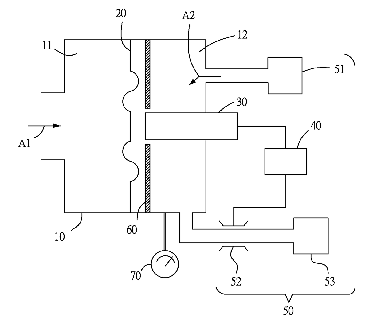
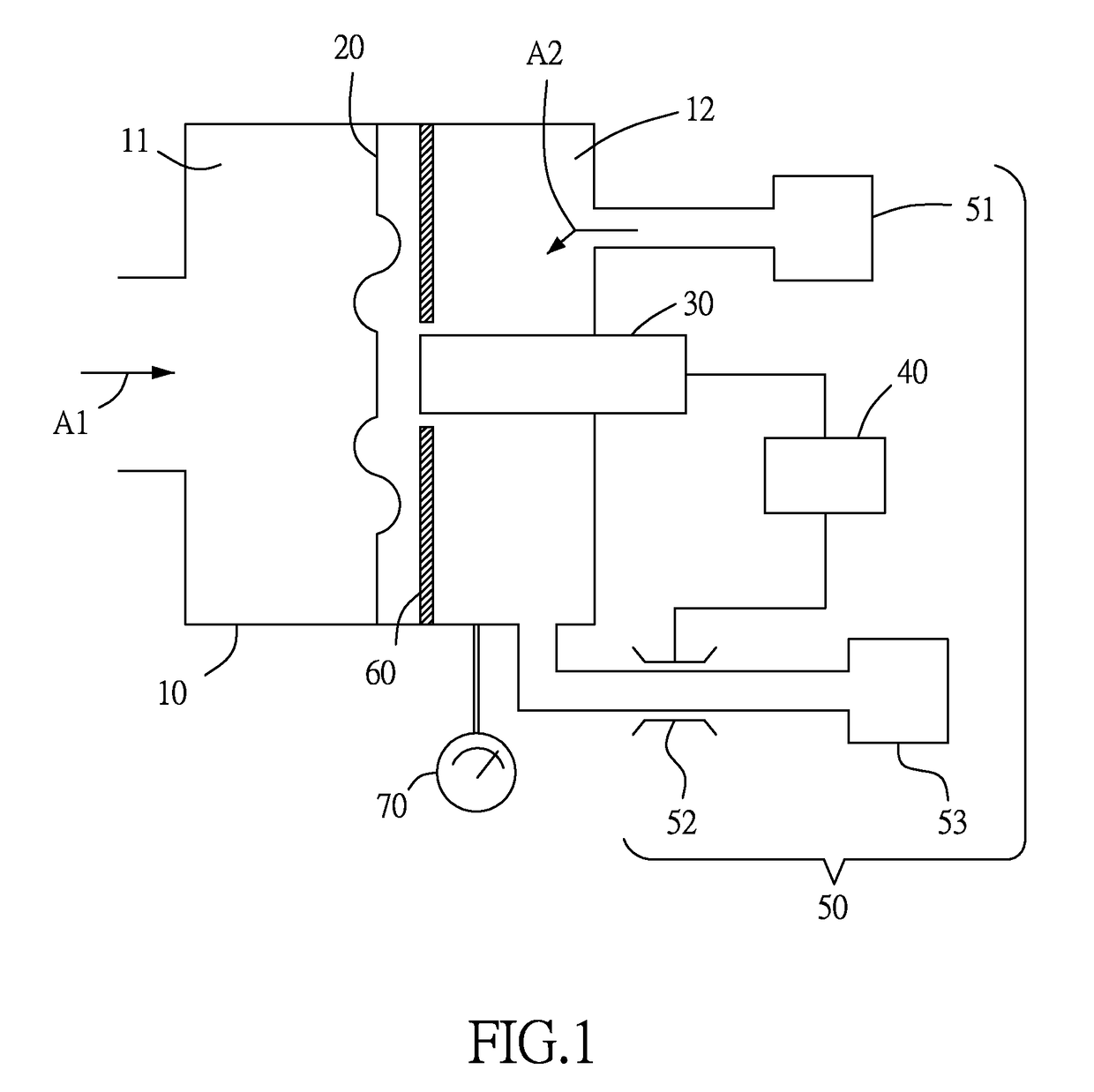
[0020]Referring to FIG. 1, there is shown a schematic view of a high-temperature gas pressure measuring device according to an embodiment of the present invention. The high temperature gas pressure measuring device comprises a pressure measuring gas housing 10, a metal diaphragm 20, a non-contact displacement sensor 30, a controller 40 and a gas regulation module 50.

[0021]The metal diaphragm 20 is disposed in the pressure measuring gas housing 10 to divide the pressure measuring gas housing 10 into a pressure measuring room 11 and a pressure referring room 12. The metal diaphragm 20 is made of a corrosion-resistant and heat-resistant material as needed. The metal diaphragm 20 is thin and ripple shaped to thereby reduce its thermal stress and deformed which might otherwise occur because of the difference in temperature between the pressure measuring room 11 and the pressure referring room 12 which are separated by the metal diaphragm 20, reduce diaphragm vertical elastic rigidity, an...


PUM

PropertyMeasurementUnit
temperatureaaaaaaaaaa

Abstract

A high-temperature gas pressure measuring method includes a pressure measuring gas housing dividing step for dividing a pressure measuring gas housing into a pressure measuring room and a pressure referring room by a metal diaphragm; a gas introducing step for introducing high temperature gas into the pressure measuring room and introducing a reference pressure gas into the pressure referring room; a displacement measuring step for measuring a displacement of the metal diaphragm, wherein the displacement is caused by pressure difference between the two rooms in pressure measuring gas housing; and a pressure determining step for measuring the pressure of a high-temperature and / or corrosive to-measure pressure gas. The method dispenses with any corrosion-resistant and heat-resistant pressure sensing component and thus cuts costs.

Description

FIELD OF TECHNOLOGY[0001]The present invention relates to gas pressure measuring methods and more particularly to a high-temperature gas pressure measuring method.BACKGROUND[0002]Conventional processes often take place in a high-temperature chamber which contains a corrosive gas. For instance, a Cu / In / Ga / Se solar cell selenization process has to measure the gas pressure in the chamber to control the process and ensure stable product quality. In general, for a low-vacuum CIGS selenization process, the processing gas pressure ranges from medium vacuum to rough vacuum, i.e., 10e-2˜760 torr and an operating temperature of 300° C.˜680° C.[0003]The operating temperature of a conventional vacuometer or pressure gauge (say US 20040089073) for measuring the chamber gas pressure is limited by the heat resistance characteristics of related elements and the materials which the inner part of the conventional vacuometer or pressure gauge is made of. Furthermore, the pressure gauge for a high-temp...

Claims


Application Information

Patent Timeline
Patent Type & Authority Patents(United States)
IPC IPC(8): G01L11/00G01L27/00
CPCG01L27/002G01L11/006G01L9/007G01L9/0076G01L19/04
Inventor WANG, YIH-HSINGPAN, WEN-CHUEHLIN, MING-JUNELI, JEN-CHIEHWU, TIEN-FUCHEN, TSAN-TUNG
Owner NAT CHUNG SHAN INST SCI & TECH
Why Eureka
Try Eureka