Process for horizontal coating of intrinsic silicon based on LPCVD technique

A process method, intrinsic silicon technology, applied in metal material coating process, gaseous chemical plating, sustainable manufacturing/processing, etc., can solve problems such as uneven coating, gas turbulence, increased burden, etc., and achieve grain size Uniformity, small disturbance, and the effect of reducing gas turbulence

Inactive Publication Date: 2020-06-16
SHENZHEN LAPLACE ENERGY TECH CO LTD
View PDF3 Cites 1 Cited by
  • Summary
  • Abstract
  • Description
  • Claims
  • Application Information

AI Technical Summary

Problems solved by technology

However, in the traditional LPCVD-based coating technology, silicon wafers are vertically inserted, such as figure 1 As shown, in the context of the increasing size of silicon wafers in the current crystalline silicon solar cell industry, the vertical insertion method presents many inconveniences. First of all, the current ins

Method used


Image

  • Process for horizontal coating of intrinsic silicon based on LPCVD technique
  • Process for horizontal coating of intrinsic silicon based on LPCVD technique
  • Process for horizontal coating of intrinsic silicon based on LPCVD technique

Examples


Embodiment 1

[0029] Step 1: Using as figure 2 In the way shown, the silicon wafers are loaded into the quartz boat by inserting the wafers horizontally, and the boat enters the quartz boat with the silicon wafers into the coated quartz tube at a set temperature of 500°C to keep the silicon wafers in a horizontal state. While entering the boat, 2000sccm-3000sccm of protective nitrogen gas is introduced.

[0030] Step 2: After the boat is in place, seal the furnace body, raise the temperature to 520°C, close the nitrogen inlet valve, and control the pressure in the furnace to a specific pressure of 500mtorr with a Roots pump. figure 1 It is the intrinsic silicon coating rate diagram at 520°C-620°C, and the corresponding temperature can be selected according to different rate requirements in this temperature range.

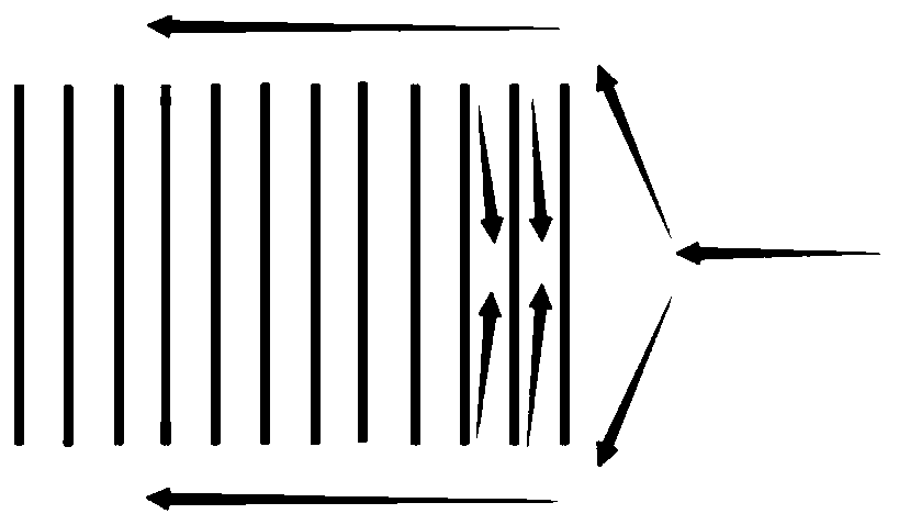
[0031] Step 3: Introduce silane into the air inlet of the furnace mouth and the furnace tail respectively, the silane flow rate is 100sccm-300sccm, and lasts for 5-10min. Among...

Embodiment 2

[0046] Step 1: Using as figure 2 In the way shown, the silicon wafers are loaded into the quartz boat by inserting the wafers horizontally, and the boat enters the quartz boat with the silicon wafers into the coated quartz tube at a set temperature of 500°C to keep the silicon wafers in a horizontal state. While entering the boat, 2000sccm-3000sccm of protective nitrogen gas is introduced.

[0047] Step 2: After the boat is in place, seal the furnace body, raise the temperature to 620°C, close the nitrogen inlet valve, and use a Roots pump to control the pressure in the furnace to a specific pressure of 450mtorr.

[0048] Step 3: Introduce silane into the air inlet of the furnace mouth and the furnace tail respectively, the silane flow rate is 100sccm-300sccm, and lasts for 5-10min. Among them, the furnace mouth is taken as Figure 4 The air intake is annular in the shown furnace mouth flange, and the annular air intake pipe 101 is bent into a semicircle and welded on the in...

Embodiment 3

[0055] Step 1: Using as figure 2 In the way shown, the silicon wafers are loaded into the quartz boat by inserting the wafers horizontally, and the boat enters the quartz boat with the silicon wafers into the coated quartz tube at a set temperature of 500°C to keep the silicon wafers in a horizontal state. While entering the boat, 2000sccm-3000sccm of protective nitrogen gas is introduced.

[0056] Step 2: After the boat is in place, seal the furnace body, raise the temperature to 580°C, close the nitrogen inlet valve, and at the same time, the Roots pump controls the pressure in the furnace to a specific pressure of 300mtorr.

[0057] Step 3: Introduce silane into the air inlet of the furnace mouth and the furnace tail respectively, the silane flow rate is 100sccm-300sccm, and lasts for 5-10min. Among them, the furnace mouth is taken as Figure 4 The air intake is annular in the shown furnace mouth flange, and the annular air intake pipe 101 is bent into a semicircle and we...


PUM


Abstract

The invention provides a process for horizontal coating of intrinsic silicon based on an LPCVD technique. The process comprises the steps that oxidized intrinsic silicon is horizontally placed in quartz boats spaced from each other by a certain distance back to back, a furnace body is sealed, the temperature is increased, silicane is guided into the furnace body for a reaction, and nitrogen is guided into the furnace body to repel a precursor; the temperature is decreased, and the pressure returns; and the quartz boats containing silicon wafers are pulled out of a furnace tube. According to the process for horizontal coating of the intrinsic silicon based on the LPCVD technique, a horizontal wafer-insertion coating process is adopted, and compared with vertical coating, gas turbulence in the tube can be reduced, and the coating uniformity in the wafers is guaranteed; and the wafers are horizontally inserted and are horizontally overlapped by means of gravity, so that the wafers are arranged stably, the disturbance of high temperature, air flow and vibrations on the horizontally-inserted silicon wafers is small, and slight raydent coating is generated on the back sides of the silicon wafers by the air flow.

Description

technical field [0001] The invention relates to the field of crystalline silicon solar cell manufacturing, in particular to a silicon wafer coating process based on low-pressure vapor deposition technology in the crystalline silicon solar cell manufacturing process. Background technique [0002] With the development of crystalline silicon solar cell technology, the cell efficiency is getting closer and closer to the theoretical and practical limits. In the traditional cell structure, there is a serious recombination of metal and semiconductor contact areas, which has become an important factor restricting the development of crystalline silicon solar cell efficiency. As a feasible solution to reduce contact recombination loss, passivated contact technology can greatly improve the efficiency of crystalline silicon solar cells, and is being paid close attention by researchers. Theoretically, a passivation contact structure is formed on the semiconductor surface, which has dual...

Claims


Application Information

Patent Timeline
IPC IPC(8): C23C16/458C23C16/455C23C16/24C23C16/52H01L31/18
CPCC23C16/24C23C16/45563C23C16/45565C23C16/4583C23C16/52H01L31/1804H01L31/1868Y02P70/50
Inventor 林佳继范伟张耀刘群张武林依婷
Owner SHENZHEN LAPLACE ENERGY TECH CO LTD
Why Eureka
Try Eureka