Method to compensate for errors in time-of-flight range cameras caused by multiple reflections

a time-of-flight range and camera technology, applied in distance measurement, surveying and navigation, instruments, etc., can solve the problems causing the state-of-the-art time-of-flight (top) camera to suffer from erroneous measurements, etc., to achieve the highest possible lateral resolution, the effect of lowering the lateral resolution

Active Publication Date: 2016-05-03
AMS SENSORS SINGAPORE PTE LTD
View PDF8 Cites 21 Cited by
  • Summary
  • Abstract
  • Description
  • Claims
  • Application Information

AI Technical Summary

Benefits of technology

[0005]Applying two different field-of-illuminations enables to keep the high lateral resolution of a typical TOF camera and at the same time reduce to error of multi-path, as typically achieved by a lower resolution image.

Problems solved by technology

Due to their parallel illumination and acquisition for all the pixels, today's state-of-the-art time-of-flight (TOP) range cameras suffer from erroneous measurements caused by multiple reflections in the scene.

Method used


Image

  • Method to compensate for errors in time-of-flight range cameras caused by multiple reflections
  • Method to compensate for errors in time-of-flight range cameras caused by multiple reflections
  • Method to compensate for errors in time-of-flight range cameras caused by multiple reflections

Examples


Embodiment Construction

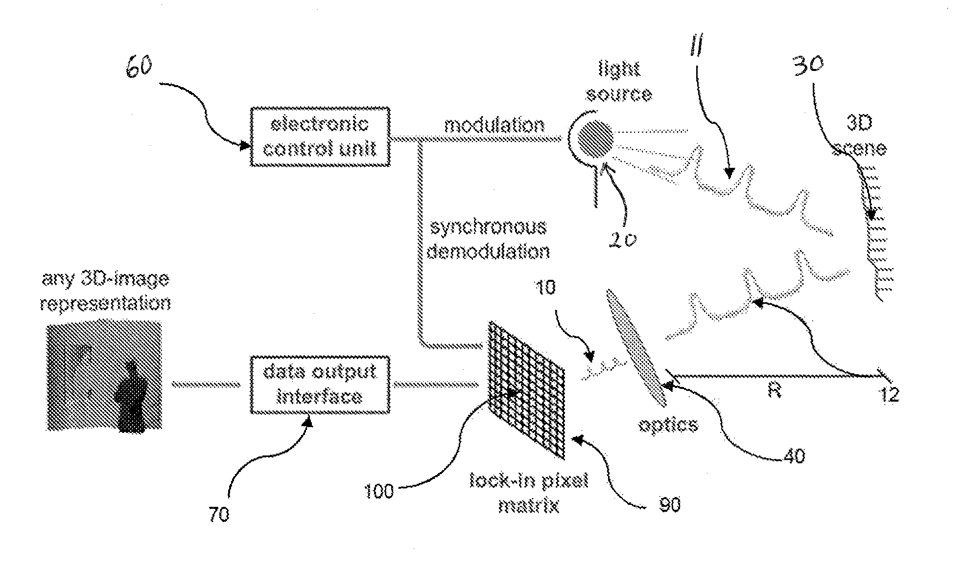
[0017]Modulated illumination light 11 from an illumination module or light source 20 is sent to the object 30 of a scene. A fraction of the total optical power sent out is reflected to the camera, through the optics 40 and detected by the 3D imaging sensor 90. The sensor 90 comprises a two dimensional pixel matrix of the demodulation pixels 100. Each pixel 100 is capable of demodulating the impinging light signal 10. An electronics. control unit 60 controls the timing of the illumination 20 and sensor 100. The demodulation values allow for each pixel to compute the time-of-flight, which, in turn, directly corresponds to the distance information of the corresponding point in the scene. The two-dimension gray scale image with the distance information is converted into a three-dimensional image by image processor IP. This can he displayed to a user via display D or used as a machine vision input.

[0018]The distance R for each pixel is calculated by

R=(c*TOF) / 2,

with c as light velocity an...


PUM


Abstract

Due to their parallel illumination and acquisition for all the pixels, today's state-of-the-art time-of-flight (TOF) range cameras suffer from erroneous measurements caused by multiple reflections in the scene. The invention proposes to compensate for the multi-path fusing the results obtained by applying two spatially different illumination schemes, typically one to achieve highest possible lateral resolution and for the second one structuring the emitted light and by doing so lowering the lateral resolution but limiting the impact of multiple reflections.

Description

RELATED APPLICATIONS[0001]This application claims the benefit under 35 USC. 119(e) of U.S. Provisional Application No. 61 / 569,451, filed on Dec. 12, 2011, which is incorporated herein by reference in its entirety.BACKGROUND OF THE INVENTION[0002]3D time-of-flight (TOP) cameras are active optical depth measurement systems. In general, TOF systems are based on the phase-measurement technique of emitted intensity-modulated light, which is reflected by the scene. The reflected light is imaged onto a sensor. The photo-generated electrons are demodulated in the sensor. Based on the phase information, the distance for each pixel is deduced. A more detailed description is presented by Oggier et al. in “An all-solid-state optical range camera for 3D real-time imaging with sub-centimeter depth resolution (SwissRanger)”, Proc. Of the SPIE, Vol. 5249, pp. 534-545, 2004.SUMMARY OF THE INVENTION[0003]Due to their parallel illumination and acquisition for all the pixels, today's state-of-the-art t...

Claims


Application Information

Patent Timeline
Patent Type & Authority Patents(United States)
IPC IPC(8): G01C3/08G01S17/36G01S17/89G01S7/491G01S7/4911G01S7/4915G01S17/894
CPCG01C3/08G01S7/4911G01S7/4915G01S17/36G01S17/89G01S17/894
Inventor OGGIER, THIERRY
Owner AMS SENSORS SINGAPORE PTE LTD
Why Eureka
Try Eureka