Dual-state steering wheel/input device

a steering wheel and input device technology, applied in the direction of vehicle position/course/altitude control, process and machine control, instruments, etc., can solve the problems of legal question surrounding the operation of the vehicle, the possibility of mode confusion, and the driver or the system developers being at fault, so as to eliminate any further pinch points, eliminate the possibility of pinch points, and access quickly, easily and safely

Active Publication Date: 2016-05-10
VOLKSWAGEN AG +1
View PDF16 Cites 73 Cited by
  • Summary
  • Abstract
  • Description
  • Claims
  • Application Information

AI Technical Summary

Benefits of technology

[0018]The current invention introduces a transforming input device (e.g., steering wheel) that has two distinct states directly linked to the current driving mode of the vehicle. In the first state, the driver is presented with a conventional steering wheel with which to steer the vehicle and manipulate common infotainment features such as, for example, audio volume. Upon entering the second state, when the vehicle enters the autonomous mode, the steering wheel rim disengages from the rest of the steering wheel mechanism and moves away from the driver, while the controls traditionally located on the spokes of the steering wheel move towards the driver. While the vehicle turns during autonomous operation, the steering wheel rim turns as well while in the retracted position. The controls, now in front of the driver and no longer rotating with the rest of the steering wheel, offer expanded infotainment interaction, facilitated by a set of fully programmable touch screens.
[0027]According to certain exemplary aspects of the invention, a steering wheel is adapted into a dual-state input device, where one state is used in the context of manual driving and allows limited use of electronic features of the vehicle and the second state is used in the context of autonomous driving and allows expanded infotainment interaction. In use, the steering wheel splits in two, the wheel rim drops back, and the wheel hub moves forward. The wheel rim serves as an indication of autonomous capability as it turns in its retracted position. The physical transformation and coinciding graphics change, limit, and expand interactive features between modes. The design of the system keeps the driver in a position of responsibility at all times. Lastly, spring loaded hinges help prevent pinch points when wheel parts mate back together. Accordingly, besides disambiguating between autonomous and manual driving modes and, thereby, decreasing the chances of mode confusion-related accidents, the transforming steering controls encourage the driver to keep his / her hands on the steering wheel at all times.

Problems solved by technology

As with existing semi-autonomous vehicles, such as commercial airliners, the most common cause of accidents in semi-autonomous automobiles will likely be some form of mode confusion.
Confusion about what driving mode the vehicle is in (autonomous or manual) may lead the driver to believe that the driver is not responsible for driving when the driver actually is responsible.
Another problem in the realm of semi-autonomous vehicles is the legal question surrounding the operation of the vehicle.
Specifically, the issue of who is at fault should an accident occur when the vehicle is in any form of autonomous mode.
Specifically, whether the drivers or the developers of the system would be at fault.
While the transforming steering controls in this case do inevitably serve to indicate an autonomous mode change, the controls neither retain nor gain any functionality in their autonomous mode state.
When the wheel is gone, the driver cannot drive.
There are currently no conventional steering wheel devices, operating as dual-state input devices, that successfully disambiguate between autonomous and manual driving modes while encouraging the driver to keep his / her hands on the steering wheel at all times.

Method used


Image

  • Dual-state steering wheel/input device
  • Dual-state steering wheel/input device
  • Dual-state steering wheel/input device

Examples


Embodiment Construction

[0042]Referring now to the drawings, and more particularly to FIGS. 4-12, there are shown exemplary embodiments of the method and structures according to the present invention.

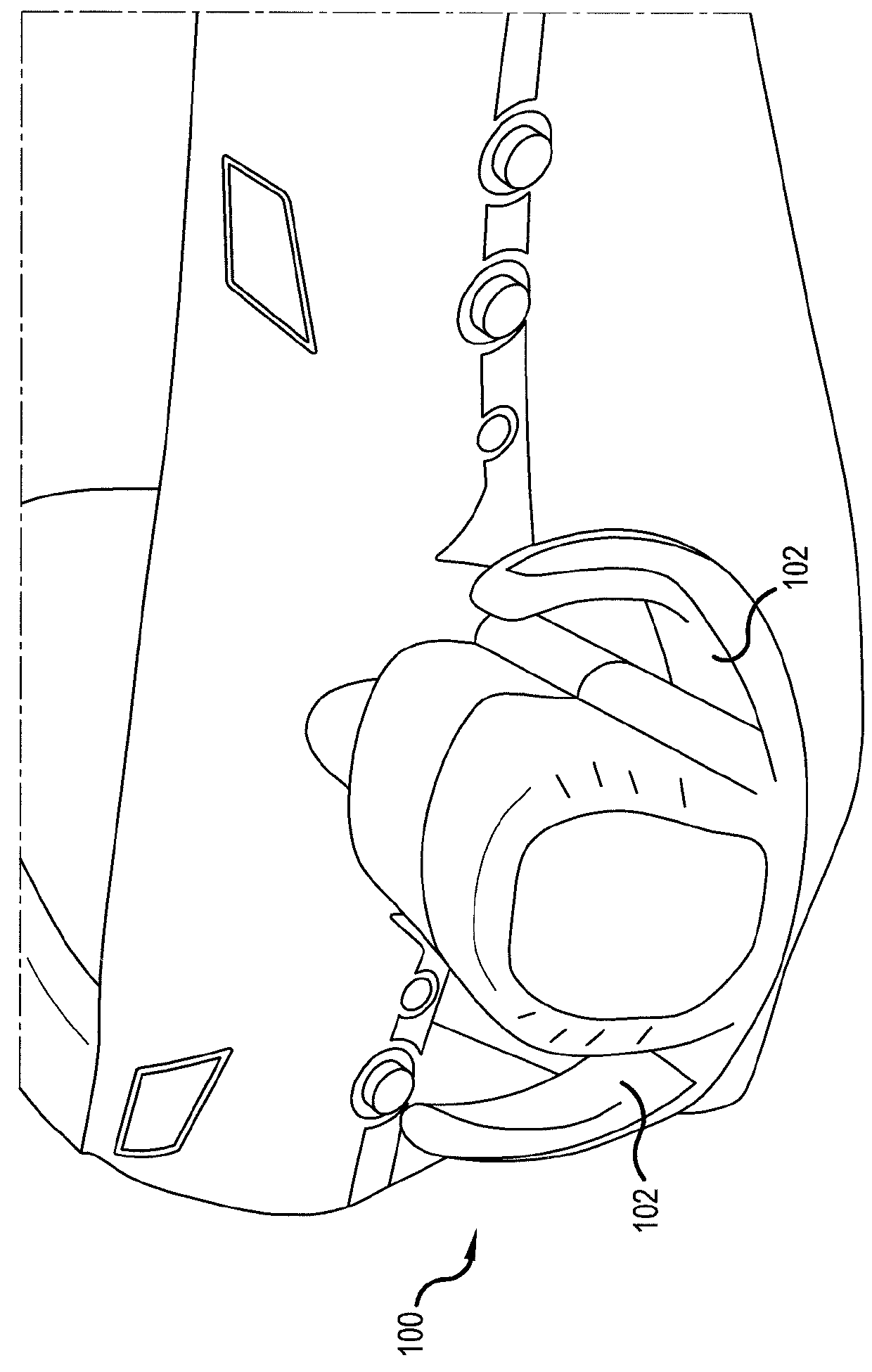
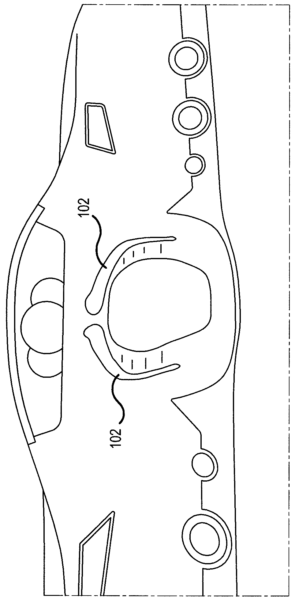
[0043]FIGS. 4 and 5 illustrate a steering wheel 400 according to certain exemplary embodiments of the present invention. The steering wheel 400 is configured to operate as a transformable, dual-state input device. The steering wheel 400 has two distinct operating states directly linked to a current driving mode of the vehicle. In a first state, which corresponds to a manual vehicle driving mode, the steering wheel 400 is presented as a conventional steering wheel. The steering wheel 400 includes a wheel rim 402 and a main body portion (i.e., central hub) 404 positioned within the wheel rim 402. The wheel rim 402 is a physically separable component from the central hub 404 and is slidably mounted along a steering column 408. The central hub 404 is mounted to an end of the steering column 408.

[0044]The steering ...


PUM


Abstract

A steering wheel is configured as a dual-state input device configured to operate in two distinct states based on a current driving mode. In a manual driving mode, the input device is configured to control a limited set of vehicle functions and in an autonomous mode the input device is configured to control an expanded set of vehicle functions. The steering wheel includes a wheel rim movably mounted on a steering column and a hub disposed within a center of the wheel rim on the steering column, the main body portion comprising an interactive touch screen disposed on the main body portion. The wheel rim is configured to disengage from the hub and move along the steering column to a retracted position.

Description

[0001]This nonprovisional application claims priority to U.S. Provisional Application No. 61 / 792,239, which was filed on Mar. 15, 2013, and which is herein incorporated by reference.BACKGROUND OF THE INVENTION[0002]1. Field of the Invention[0003]The present invention relates to vehicle steering wheel devices and, more particularly, to a dual-state steering wheel for use in a manual driving mode and an autonomous driving mode.[0004]2. Description of the Background Art[0005]As vehicles' driver assistance systems gain in complexity and approach, semi-autonomous capability, it is increasingly vital that the driver of such a vehicle be aware of the current autonomous system state. As with existing semi-autonomous vehicles, such as commercial airliners, the most common cause of accidents in semi-autonomous automobiles will likely be some form of mode confusion. Confusion about what driving mode the vehicle is in (autonomous or manual) may lead the driver to believe that the driver is not ...

Claims


Application Information

Patent Timeline
Patent Type & Authority Patents(United States)
IPC IPC(8): B62D1/04G05D1/00B62D1/06B62D1/28B60K37/06
CPCB62D1/04B60K37/06B62D1/046B62D1/06B62D1/286B60K2350/928Y10T74/20256B60K2370/197B60K2370/175B60K2370/782
Inventor LATHROP, WILLIAM BRIANTOGGWEILER, JAMES LEIGHGLASER, ERIK ROBERTCOSER, NATHANIEL ROBERTGRANT, BRYAN
Owner VOLKSWAGEN AG
Why Eureka
Try Eureka