Terminal structure and electrical connector having the same

a technology of terminal structure and electrical connector, which is applied in the direction of coupling device connection, two-part coupling device, electrical apparatus, etc., can solve the problems of shortening the service life of the die, increasing the complexity of the die, and slowing down the manufacturing process, so as to improve the resonance, reduce the loss of signal, and adjust the impedance

Inactive Publication Date: 2016-05-10
ALL BEST PRECISION TECH
View PDF31 Cites 64 Cited by
  • Summary
  • Abstract
  • Description
  • Claims
  • Application Information

AI Technical Summary

Benefits of technology

[0016]Accordingly, the present invention provides a terminal structure and an electrical connector having the terminal structure, which are capable of improving resonance, adjusting impedance, reducing signal loss, simplifying die structures, extending the service life of a die, speeding up a manufacturing process, and simplifying the process flow of a manufacturing process.

Problems solved by technology

However, as far as the terminal of a conventional electrical connector is concerned, ground terminals are predisposed to resonance for lack of electrical connection therebetween.
Also, in the situation where the terminal is enclosed in part and then exposed in part, its inherent drawbacks are as follows: first, a plastic structure encloses a portion of the terminal and thus precludes a reduction in signal loss; second, after a portion of the terminal has been enclosed, the process of exposing another portion of the terminal entails enclosing a portion of the terminal with a plastic structure and then removing a portion of the plastic structure with a die, and in consequence the process increases the complexity of a die, shortens the service life of a die, slows down a manufacturing process, and increases the complexity of the process flow of a manufacturing process.

Method used


Image

  • Terminal structure and electrical connector having the same
  • Terminal structure and electrical connector having the same
  • Terminal structure and electrical connector having the same

Examples


Embodiment Construction

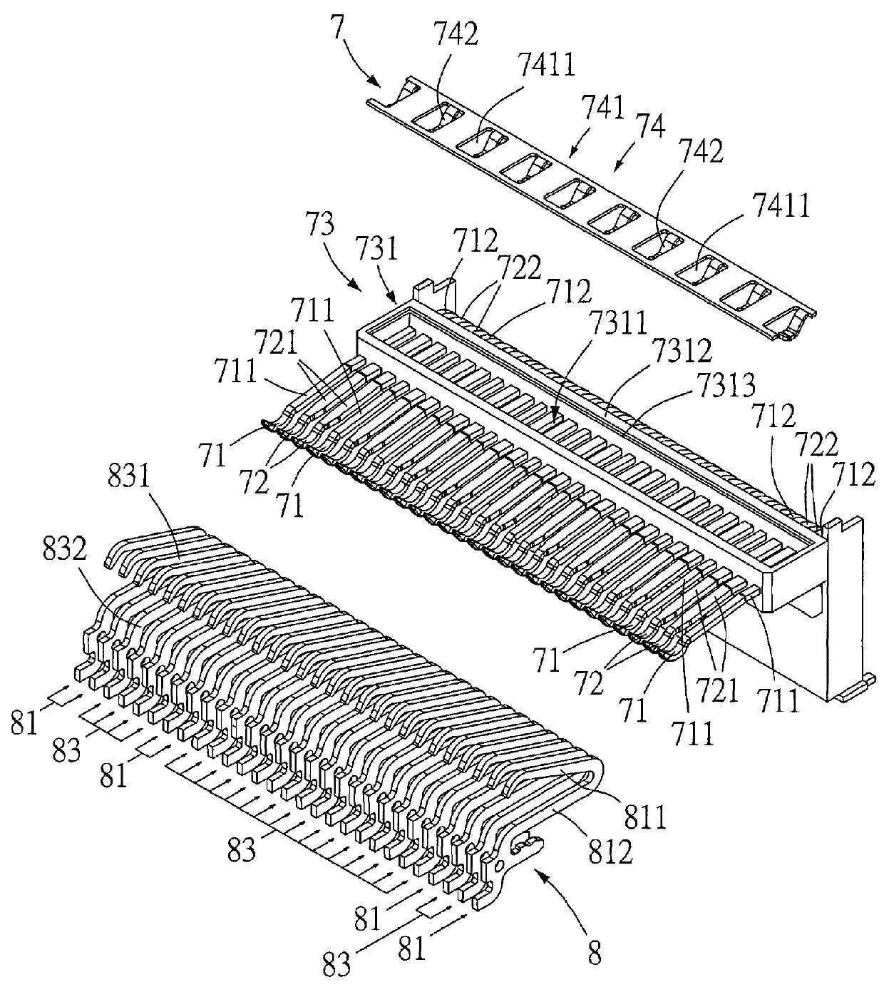
[0030]Referring to FIG. 1, the present invention in the first aspect provides a terminal structure 7 which comprises a plurality of ground terminals 71, a plurality of signal terminals 72, a connection element 73, and a ground electrical connection element 74. The ground terminal 71 has an L shape and has a resilient ground electrical contact segment 711 and a ground electrical connection segment 712 connected to the resilient ground electrical contact segment 711. The resilient ground electrical contact segment 711 is formed by extending the ground terminal 71 horizontally. The ground electrical connection segment 712 is formed by extending the ground terminal 71 vertically. The resilient ground electrical contact segment 711 is adapted to come into electrical contact with an external plug or receptacle (not shown). The ground electrical connection segment 712 is adapted to electrically connect with a circuit board (not shown). The signal terminal 72 has an L shape and has a resili...


PUM


Abstract

A terminal structure includes ground terminals, signal terminals, connection elements, and ground electrical connection elements. The connection elements connect the ground terminals to the signal terminals, respectively. The ground electrical connection elements are in connection with connection elements and in electrical contact with at least a ground terminal. An electrical connector includes two terminal structures and a casing. The connection elements are connected to each other. An insertion slot is disposed on the front side of the casing. The terminal structure is disposed at the casing. The resilient ground electrical contact segments and the resilient signal electrical contact segments face the insertion slot. The ends of the ground electrical connection segments and the ends of the signal electrical connection segments are exposed from the casing. The terminal structure and the electrical connector improve resonance, adjust impedance, reduce signal loss, simplify die structures, and extend service life of a die.

Description

FIELD OF THE INVENTION[0001]The present invention relates to terminal structures and electrical connectors having the terminal structures, and more particularly, to a terminal structure and an electrical connector having the terminal structure, which are capable of improving resonance, adjusting impedance, reducing signal loss, simplifying die structures, extending the service life of a die, speeding up a manufacturing process, and simplifying the process flow of a manufacturing process.BACKGROUND OF THE INVENTION[0002]With data communication being sophisticated nowadays, long-range data communication relies mostly upon wireless transmission devices, whereas short-range data communication usually requires electrical connectors. The terminal of a conventional electrical connector is typically disposed in the conventional electrical connector by an insert and injection process in a manner to provide two options of configuration: first, the terminal is enclosed in part; second, the ter...

Claims


Application Information

Patent Timeline
Patent Type & Authority Patents(United States)
IPC IPC(8): H01R24/00H01R13/6471H01R12/71
CPCH01R13/6471H01R12/716H01R13/6583H01R13/6587
Inventor YANG, HAVEN
Owner ALL BEST PRECISION TECH
Why Eureka
Try Eureka