Integral storage chamber for footwear

a storage chamber and shoe technology, applied in the field of shoes, can solve the problems of user stumble and fall, limited storage volume of the heel of the shoe, and the failure of background art to provide storage in the shoe compartment, and achieve the effect of safe carrying by the user

Active Publication Date: 2016-05-17
SHUMAN ASHLEY
View PDF48 Cites 4 Cited by
  • Summary
  • Abstract
  • Description
  • Claims
  • Application Information

AI Technical Summary

Benefits of technology

[0016]In accordance with one embodiment of the present invention, the invention comprises a storage chamber disposed within a carriage that may be slidingly engaged with and located on the underneath surface of a shoe, such that a user may slide the carriage forward to an open position in order to access the storage chamber. The storage chamber may comprise a void disposed within the carriage that is exposed when the carriage is in an open position. When the carriage is in an open position the storage chamber is exposed, allowing a user to access the storage chamber in order to place or remove items therein. When the carriage is in a closed position, the storage chamber may not be exposed and thus any items stored therein may be hidden from view and safely carried by the user.
[0017]The carriage may be completely removable from the shoe. In the preferred embodiment in which the carriage is slidingly engaged with the shoe, the carriage may slide all the way off the shoe by translating the carriage toward the toe of the shoe utilizing the sliding engagement between the carriage and the shoe sole, allowing a user to completely remove the carriage for ease of access if desired. The carriage may be disposed on the underneath side of the shoe and may be slidingly engaged with the shoe by a tongue and groove sliding fit or by any manner of complementary surfaces located in the carriage or shoe sole that create a sliding engagement between the carriage and the shoe sole. The carriage may be captured in the closed position by engagement of a carriage retaining pin located on an underneath surface of the shoe sole with a retaining pin receiving recess disposed on the carriage, and in which the carriage retaining pin and retaining pin receiving recess are dimensioned such that the diameter of the carriage retaining pin and the retaining pin receiving recess form a snap fit or a slight press fit such that the pin snaps into place into the retaining pin receiving recess when the carriage is pushed towards the heel of the shoe utilizing the sliding engagement between the carriage and the shoe so that the carriage is in a closed position. This snap fit or slight press fit between the carriage retaining pin and the retaining pin receiving recess may thus retain the carriage in place during normal use of the shoe.

Problems solved by technology

The attempts to provide storage in a shoe compartment in the background art have met with limited success.
This particular approach to providing a storage compartment within a shoe suffers from the disadvantage that the rotating front portion of the shoe may unintentionally or unexpectedly become unlatched and rotate downward without warning and may cause a user to stumble and fall if it catches on a walking surface.
This particular approach to providing a storage compartment within a shoe suffers from the disadvantage that the available volume for storage is limited to the heel of the shoe and may not provide enough volume for certain items such as, for instance, credit cards.
This particular approach to providing a storage compartment within a boot or shoe suffers from the disadvantage that the rotating heel portion of the boot or shoe may cause a user to stumble and fall if it catches on a walking surface.
While this approach may be usable for a man's shoe or boot, it is not feasible for a women's shoe which comprises a narrow heel section as there is likely not enough volume available in the heel area of a typical woman's shoe, such as a high heel shoe, to allow storage of any personal objects of any appreciable size such as, for example, a credit card or set of car keys.

Method used


Image

  • Integral storage chamber for footwear
  • Integral storage chamber for footwear
  • Integral storage chamber for footwear

Examples


Embodiment Construction

[0037]The following documentation provides a detailed description of the invention.

[0038]As used herein, “normal” use of the shoe means the use of the shoe during walking, storage of the shoe, and other operations using the shoe in which the storage chamber of the invention is not accessed.

[0039]As used herein, the “closed” position of the carriage is defined as the position in which the carriage is located at the heel-most position of travel of the sliding engagement between carriage and shoe.

[0040]As used herein, the “open” position of the carriage is defined as any position in which the carriage is not located at the heel-most position of travel of the sliding engagement between carriage and shoe. Thus, the carriage may be in a partially open position or a fully open position, or may be removed from the shoe altogether in some embodiments.

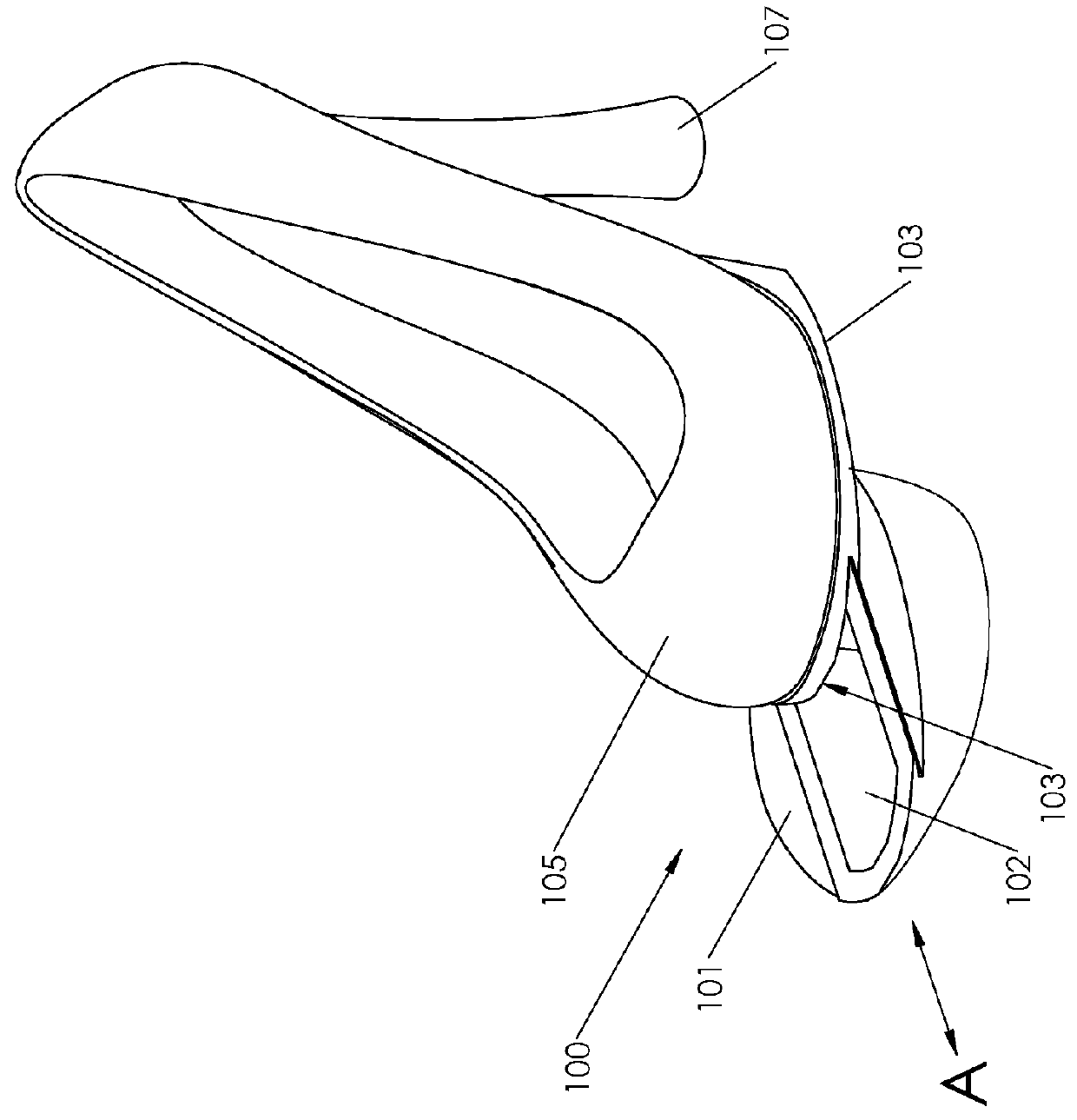
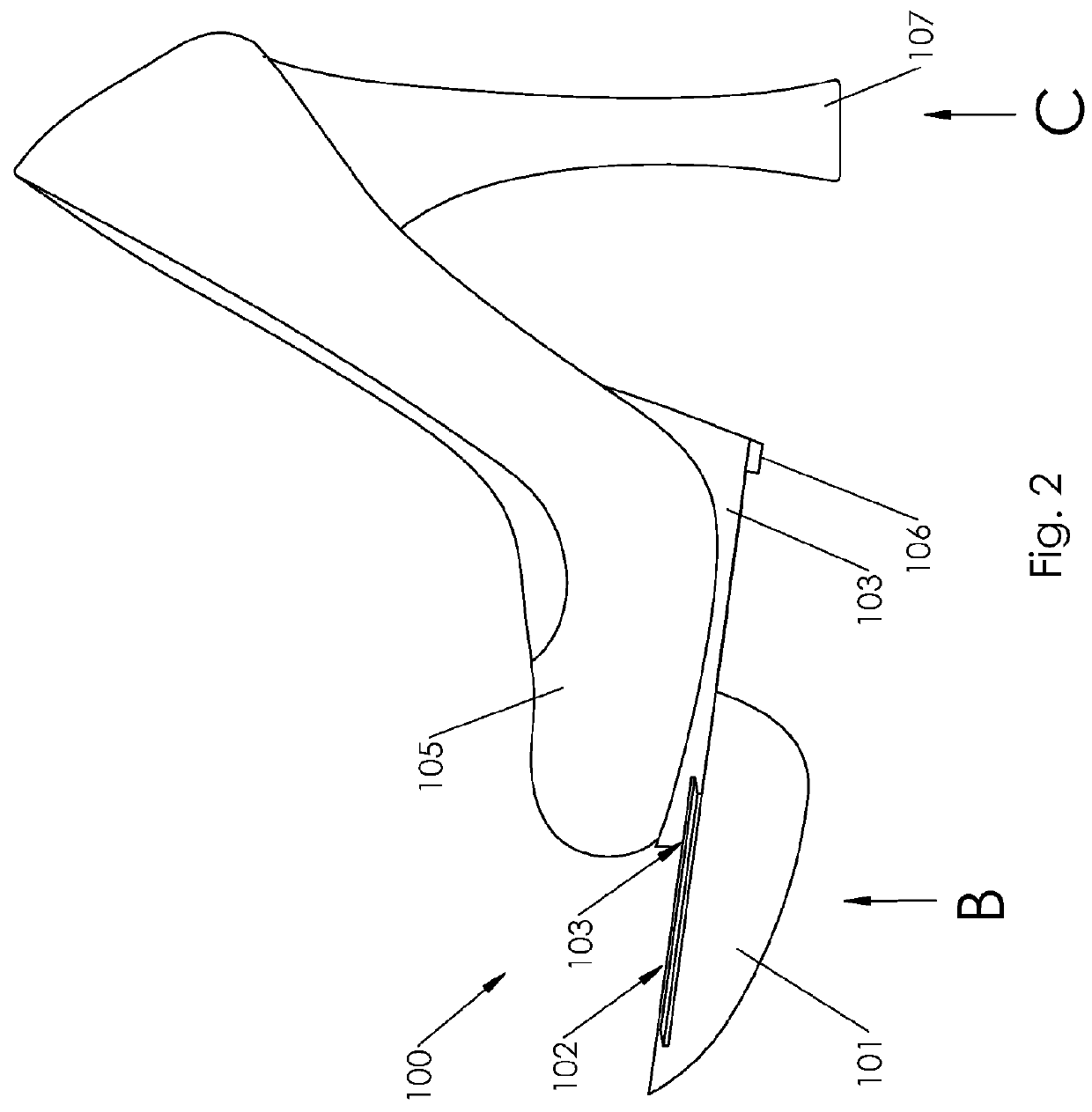
[0041]As used herein, the “toe end” or “toe side” is that end of the shoe upon which the shoe toe is located as depicted by B in FIG. 2. Also, ...


PUM


Abstract

A shoe, or shoe sole, with integral storage chamber is claimed. The invention may comprise a carriage that is in sliding engagement with the sole of a shoe, wherein the carriage further comprises a storage chamber for storing personal objects. The sliding engagement of the invention may comprise tongue and groove complementary surfaces. The carriage containing the storage chamber may translate in a direction along a longitudinal axis of the shoe and may be further retained onto the shoe by use of a retaining pin located on the shoe sole that is engaged in a press fit with retaining pin receiving recess on the carriage such that the carriage is securely retained in a closed position. A user may safely store objects in the storage chamber without detection and may access the objects quickly if needed. The invention may further comprise a mirror and closable heel storage chamber.

Description

CROSS REFERENCE TO RELATED APPLICATIONS[0001]Not applicable.STATEMENT REGARDING FEDERALLY SPONSORED RESEARCH OR DEVELOPMENT[0002]Not applicable.INCORPORATION-BY-REFERENCE OF MATERIAL SUBMITTED ON A COMPACT DISK[0003]Not applicable.BACKGROUND OF THE INVENTION[0004]1. Field of the Invention[0005]The invention is directed to the field of shoes, and more specifically is directed to a shoe, or shoe sole, which comprises an integral compartment, or chamber, for storage of items such as, by way of example and not by limitation, money, credit cards, identification cards, safety products such as pepper spray or mace, vehicle keys, house or apartment keys, or any personal or other item that the user may desire to keep close at hand for easy access. The invention is useful for any number of situations or occasions in which the storage of such personal items may be desired, but may be especially useful in certain situations, such as those occurrences when the user is in an environment in which ...

Claims


Application Information

Patent Timeline
Patent Type & Authority Patents(United States)
IPC IPC(8): A43B3/00A43B13/14A43B21/42
CPCA43B3/0031A43B13/14A43B21/42A43B3/0047
Inventor SHUMAN, ASHLEY
Owner SHUMAN ASHLEY
Why Eureka
Try Eureka