AI technical title is built by Patsnap AI team. It summarizes the technical point description of the patent document.
a technology of electric mitre saw and sliding shaft, which is applied in the direction of metal sawing device, manufacturing tools, portability drilling machines, etc., can solve the problems of large packing dimension, high delivery cost, and large working space of sliding type miter saw, so as to facilitate operation and reduce fabrication difficulty level, the effect of greatly reducing the guide rod length
Active Publication Date: 2016-05-17
SUMEC HARDWARE & TOOLS
View PDF35 Cites 1 Cited by
Summary
Abstract
Description
Claims
Application Information
AI Technical Summary
This helps you quickly interpret patents by identifying the three key elements:
Problems solved by technology
Method used
Benefits of technology
Benefits of technology
[0005]The present invention has been accomplished under the circumstances in view. It is the main object of the present invention to provide a electric mitre saw, which has the advantages of compact structure, long cutting stroke, sliding stroke adjustability, working space saving and ease of fabrication.
Problems solved by technology
During operation of a sliding type miter saw of this design, the at least one sliding rail will extend backward, and therefore the sliding type miter saw requires a large working space.
Further, a sliding type miter saw of this design has the drawbacks of large packing dimension and high delivery cost.
However, due to a single layer sliding rail arrangement, the sliding stroke is limited.
However, this design of sliding type miter saw still requires a large working space and has a large packing dimension.
This design fully utilizes the space above the base, however, the sliding rail will extend out of the base to a long distance during the operation.
Method used
Image
Click on the blue label to locate the original text in one second.
Reading with bidirectional positioning of images and text.
Examples
Embodiment Construction
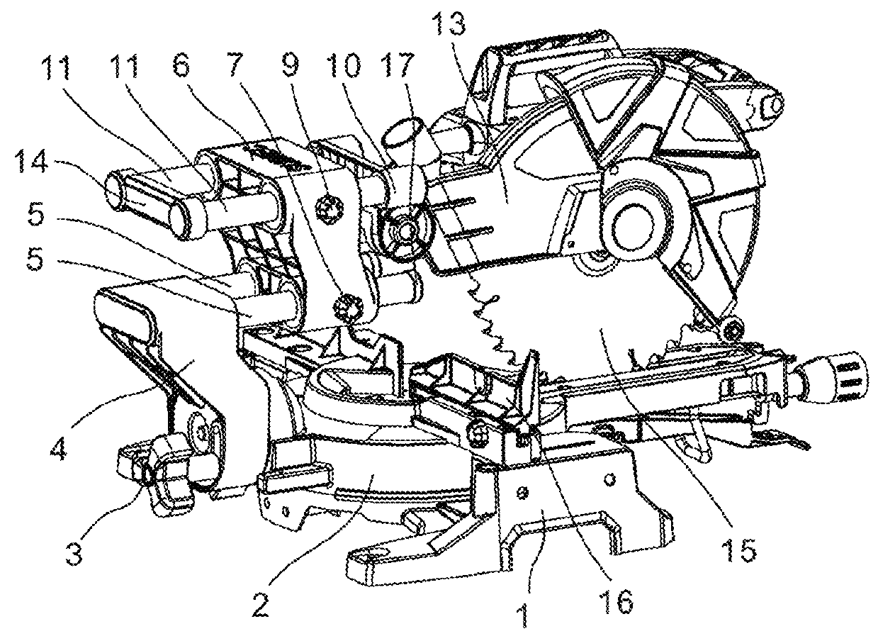
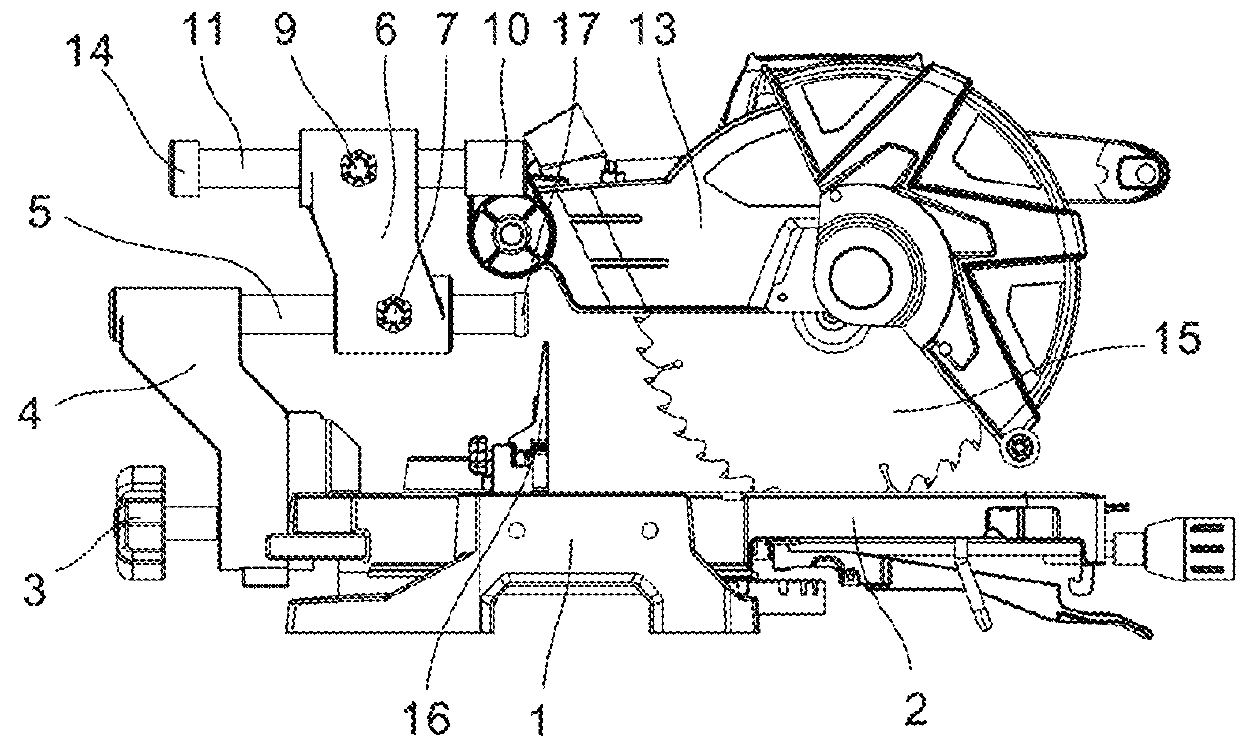
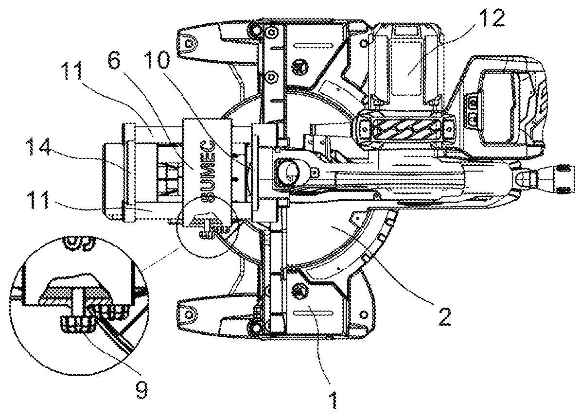
[0053]Referring to FIGS. 1, 2 and 3, a electric mitre saw in accordance with a first embodiment of the present invention is shown. According to this first embodiment, the electric mitre saw comprises a base 1, a fence 16 mounted at the base 1 for supporting the workpiece to be cut, a worktable 2 rotatably coupled to the base 1, a swinging arm 4 pivotally mounted at a rear side of the worktable 2, an arm locking knob 3 located at a rear side of the swinging arm 4 and adapted for locking the swinging arm 4 to the worktable 2 at a selected angle, at least one, for example, two first-layer guide rods 5 mounted in and horizontally extended out of the swinging arm 4, a sliding block 6 mounted on and movable along the first-layer guide rods 5, at least one, for example, two second-layer guide rods 11 slidably mounted in the sliding block 6 in parallel to the first-layer guide rods 5, a rotating shaft 10 fixedly mounted at one end of the second-layer guide rods 11, and a saw unit pivotally ...
PUM
Property
Measurement
Unit
electric
aaaaa
aaaaa
acute angle
aaaaa
aaaaa
electric mitre
aaaaa
aaaaa
Abstract
Disclosed is an electric mitre saw, comprising a base (1), a work bench (2), a saw mechanism, and a swing arm (4), wherein a plurality of layers of slide rails (5, 11) extending in a horizontal direction are provided on the swing arm (4), with the plurality of layers of slide rails (5, 11) being able to slide horizontally relative to each other by means of a slide block (6), a rotary shaft (10) is provided on one layer of the slide rails (11) farthest away from the swing arm (4), and the saw mechanism is rotatably connected to the rotary shaft (10). By means of the arrangement of the plurality of layers of slide rails (5, 11), the length of each layer of slide rails is relatively short, the manufacturing difficulty is reduced, there is a saving in the working space of the miter saw, and the packaging volume is reduced. When one layer of slide rails (5, 11) is respectively arranged at both sides of a saw blade (15), the end parts of two slide rails of each layer of slide rails (5, 11) are able to be connected by a connecting seat (8, 14), thus facilitating the improvement of parallelism of the two slide rails (5, 11), and providing a greater cutting travel. A gripping space is also formed between the two layers of slide rails (5, 11), such that observation during cutting is convenient.
Description
BACKGROUND OF THE INVENTION[0001]1. Field of the Invention[0002]The present invention relates to miter saw technology, and more particularly to a sliding type electric mitre saw.[0003]2. Description of the Related Art[0004]For the advantage of being capable of making a quick, accurate, wide crosscut in a workpiece at a selected angle, sliding type miter saws have been widely used in various fields. In the prior art, most sliding type miter saws have a swinging arm mounted at a rear side of the worktable, at least one sliding rail slidably mounted at the swinging arm, and a sawing mechanism fixedly mounted at one end of the sliding rail, thereby providing a sliding cutting function. During operation of a sliding type miter saw of this design, the at least one sliding rail will extend backward, and therefore the sliding type miter saw requires a large working space. Further, a sliding type miter saw of this design has the drawbacks of large packing dimension and high delivery cost. U....
Claims
Application Information
Patent Timeline
Application Date:The date an application was filed.
Publication Date:The date a patent or application was officially published.
First Publication Date:The earliest publication date of a patent with the same application number.
Issue Date:Publication date of the patent grant document.
PCT Entry Date:The Entry date of PCT National Phase.
Estimated Expiry Date:The statutory expiry date of a patent right according to the Patent Law, and it is the longest term of protection that the patent right can achieve without the termination of the patent right due to other reasons(Term extension factor has been taken into account ).
Invalid Date:Actual expiry date is based on effective date or publication date of legal transaction data of invalid patent.

