Supercharge Your Innovation With Domain-Expert AI Agents!

Negative air duct sump for ink removal

a technology of air duct sump and ink removal, which is applied in the direction of printing, etc., can solve the problems of affecting print quality, affecting the quality of printing, and forming of ink puddles

Active Publication Date: 2016-05-24
EASTMAN KODAK CO
View PDF12 Cites 0 Cited by
  • Summary
  • Abstract
  • Description
  • Claims
  • Application Information

AI Technical Summary

Benefits of technology

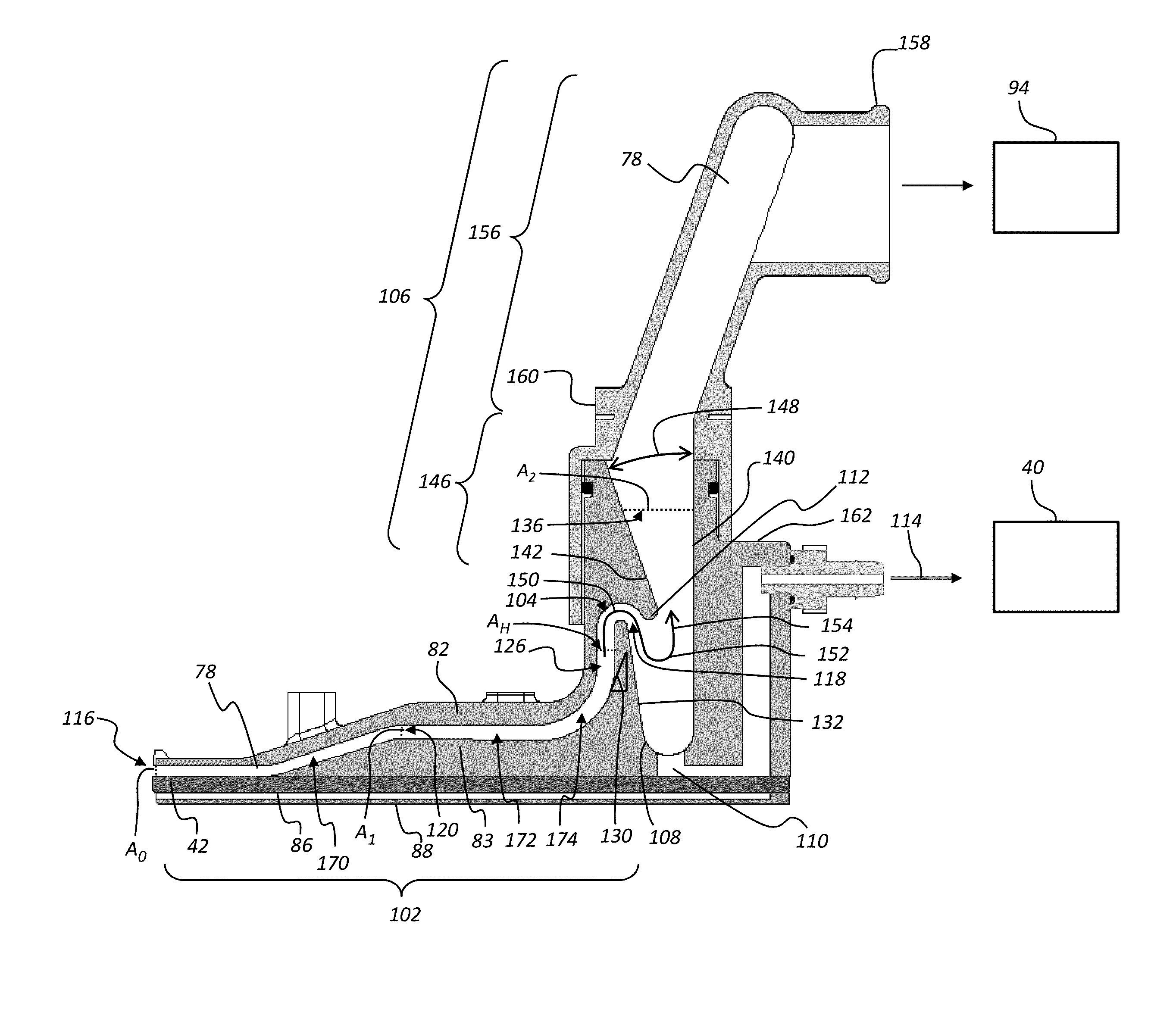
The invention prevents fluid from getting into the gas flow duct and carrying it out through the exit port. This prevents contamination of downstream components.

Problems solved by technology

Some of these drops can be deflected sufficiently by the air flow such that they enter the gas flow duct, causing ink puddles to form.
Ink from the puddles of ink in the gas flow duct can be dragged by the gas flow up into the vacuum source that is attached to the gas flow duct, possibly damaging the vacuum source.
Ink puddles can induce oscillations in the gas flow that can produce a modulation in the print drop trajectories that adversely affect print quality.
The ink can then accumulate in these regions where it eventually affects the gas flow through the duct, degrading the operation of the printhead.

Method used


Image

  • Negative air duct sump for ink removal
  • Negative air duct sump for ink removal
  • Negative air duct sump for ink removal

Examples


Embodiment Construction

[0025]The present description will be directed in particular to elements forming part of, or cooperating more directly with, apparatus in accordance with the present invention. It is to be understood that elements not specifically shown or described may take various forms well known to those skilled in the art. In the following description and drawings, identical reference numerals have been used, where possible, to designate identical elements.

[0026]The invention is inclusive of combinations of the embodiments described herein. References to “a particular embodiment” and the like refer to features that are present in at least one embodiment of the invention. Separate references to “an embodiment” or “particular embodiments” or the like do not necessarily refer to the same embodiment or embodiments; however, such embodiments are not mutually exclusive, unless so indicated or as are readily apparent to one of skill in the art. The use of singular or plural in referring to the “method...


PUM


Abstract

A gas flow duct for use in redirecting drops of liquid ejected from a printhead in a continuous inkjet printer, including a sump, a first duct portion upstream of the sump, and a second duct portion downstream of the sump. The first duct portion rises from an entrance to an apex and then turns downward and exits into the sump, and the second duct portion rises from the sump toward an exit port. A cross-sectional area of the first duct portion is adapted to produce a gas flow velocity sufficient to transport entrained liquid through the first duct portion past the apex and into the sump. A cross-sectional area of the second duct portion is larger than the cross-sectional area of the first duct portion and is adapted to produce a gas flow velocity insufficient to transport entrained liquid through the second duct portion.

Description

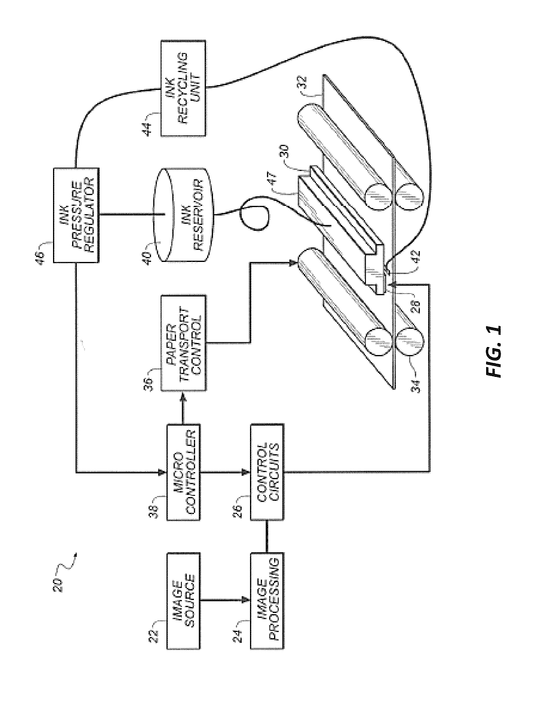
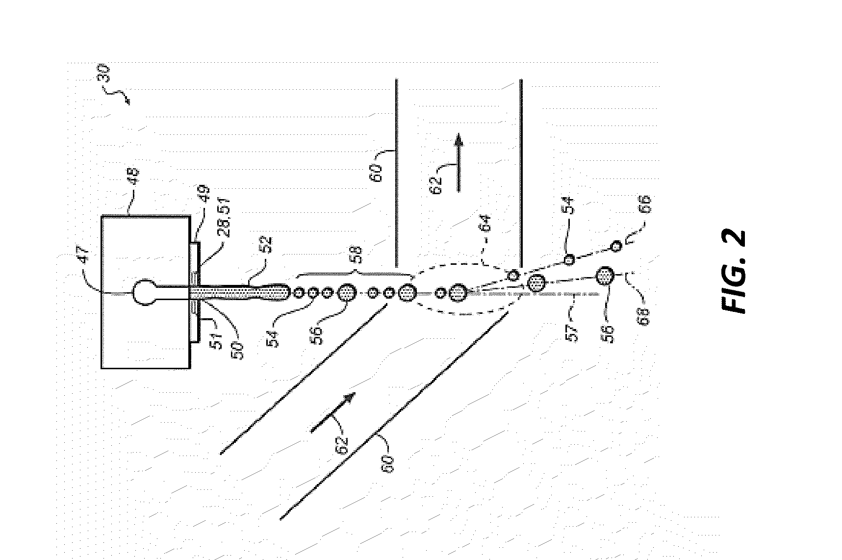
FIELD OF THE INVENTION[0001]This invention pertains to the field of digitally controlled printing devices and more particularly to continuous printing systems in which a liquid stream breaks into droplets that are deflected by a gas flow.BACKGROUND OF THE INVENTION[0002]Continuous stream inkjet printing uses a pressurized ink source to supply ink to one or more nozzles to produce a continuous stream of ink from each of the nozzles. Stimulation devices, such as heaters positioned around the nozzle, stimulate the streams of ink to break them up into drops with either relatively large volumes or relatively small volumes. These drops are then directed by one of several systems including, for example, electrostatic deflection or gas flow deflection devices.[0003]In printheads that include gas flow deflection systems, the drop deflecting gas flow is typically produced, at least in part, by a gas (e.g., air) being drawn laterally across the drop trajectories into a negative gas flow duct a...

Claims


Application Information

Patent Timeline
IPC IPC(8): B41J2/185B41J2/02
CPCB41J2/02B41J2002/1853B41J2/03B41J2002/031B41J2002/033B41J2/105
Inventor PIATT, MICHAEL J.TUNMORE, DAVID F.
Owner EASTMAN KODAK CO
Features
  • R&D
  • Intellectual Property
  • Life Sciences
  • Materials
  • Tech Scout
  • Unparalleled Data Quality
  • Higher Quality Content
  • 60% Fewer Hallucinations
Learn More