
Firmware ROM patch method

a technology of rom patch and firmware, applied in the field of firmware rom patch method, can solve the problems of difficult, time-consuming, difficult, and expensive revisions of any such device, and rarely has a well-established mechanism for updating itself to fix bugs or address functionality issues

Active Publication Date: 2016-05-24
MICROCHIP TECH INC
View PDF61 Cites 10 Cited by
  • Summary
  • Abstract
  • Description
  • Claims
  • Application Information

AI Technical Summary

Problems solved by technology

Even though in many respects firmware is as much a software component of a working system as the operating system, unlike most modern operating systems, firmware rarely has a well established mechanism for updating itself to fix bugs or addressing functionality issues that are detected after a system that operates according to the firmware is shipped.
As a result, much of the hardware currently on the market is unable to function in any useful way until the host computer has loaded onto it the requisite firmware.
Making modifications to firmware that is stored in an on-chip ROM typically requires a re-spin (metal layer change) to that device, making revisions to any such device expensive, time consuming, and difficult.
However, the program RAM requirement precludes many single-chip solutions, since most microcontrollers have insufficient or non-existent program RAM.
While some 32-bit microcontrollers and some Digital Signal Processors (DSPs) could run TOF in single chip mode, TOF would have to be ported to them, a task that could prove expensive and possibly time consuming.
While the above referenced solutions address the issue of patching firmware stored in a ROM, they can be costly and / or inefficient.
For example, the need for jump tables with function pointers is space inefficient because function pointers occupy more space.

Method used


Image

  • Firmware ROM patch method
  • Firmware ROM patch method
  • Firmware ROM patch method

Examples


Embodiment Construction

[0027]As used herein, a “set of instructions” may refer to one or more instructions. More specifically, in some embodiments, “instructions” may refer to programming code, software, and / or functions implemented in the form of a code that is executable by a controller, microprocessor, and / or custom logic circuit adapted to execute these instructions. In some embodiments, these instructions may comprise device drivers, control software, and / or machine code.

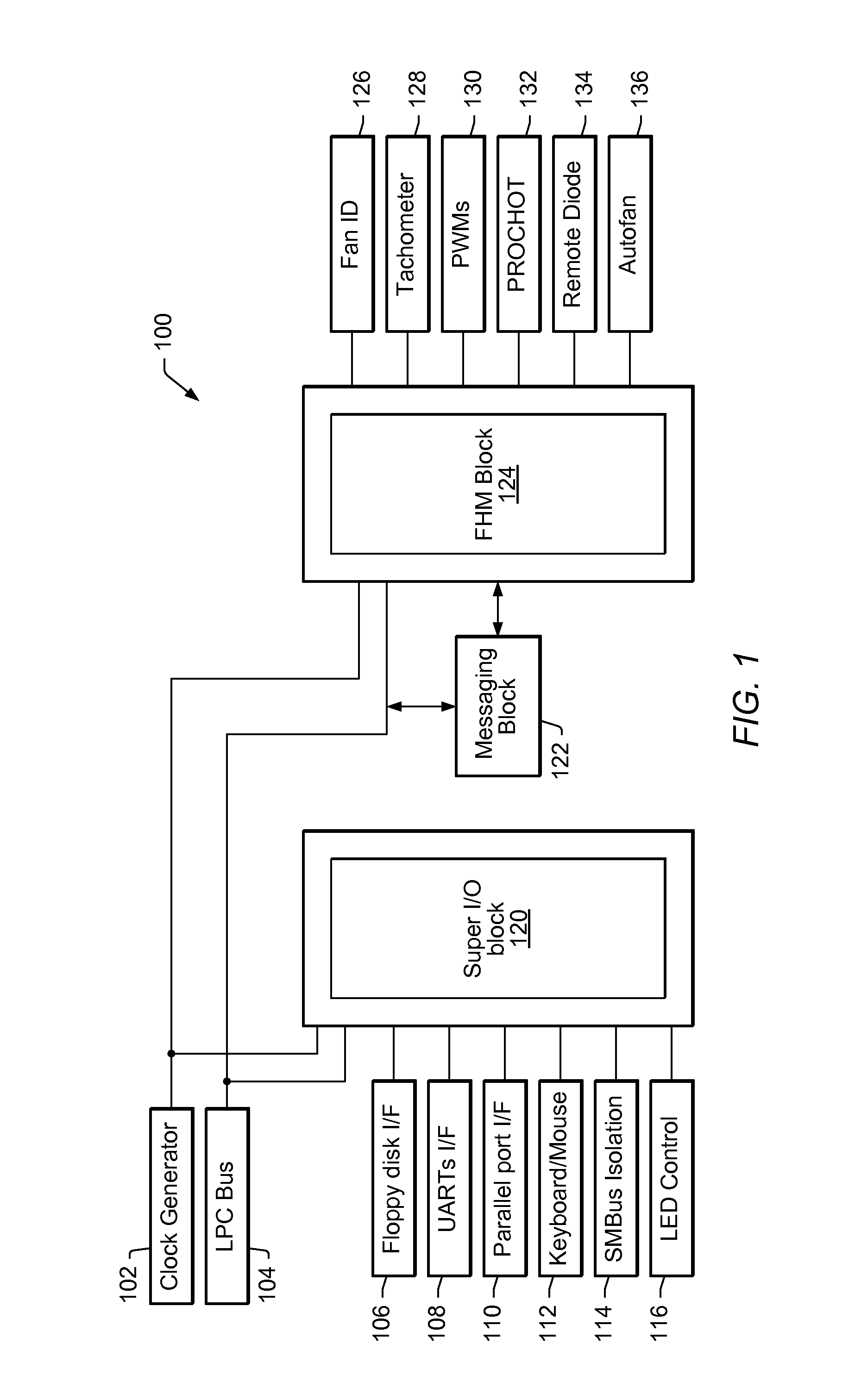
[0028]In one set of embodiments, a functional block 100, which is shown in FIG. 1 and may be an integrated circuit (IC), may be configured to provide fan control, hardware monitoring, and / or super input / output (I / O) functionality within a computer system. A hardware based Super Input / Output (I / O) portion 120 of the IC may operate ports configured to control devices including but not limited to one or more of parallel port devices 110, floppy disks 106, keyboard and mouse 112, Universal Asynchronous Receiver / Transmitters (UARTs) 108, ...


PUM


Abstract

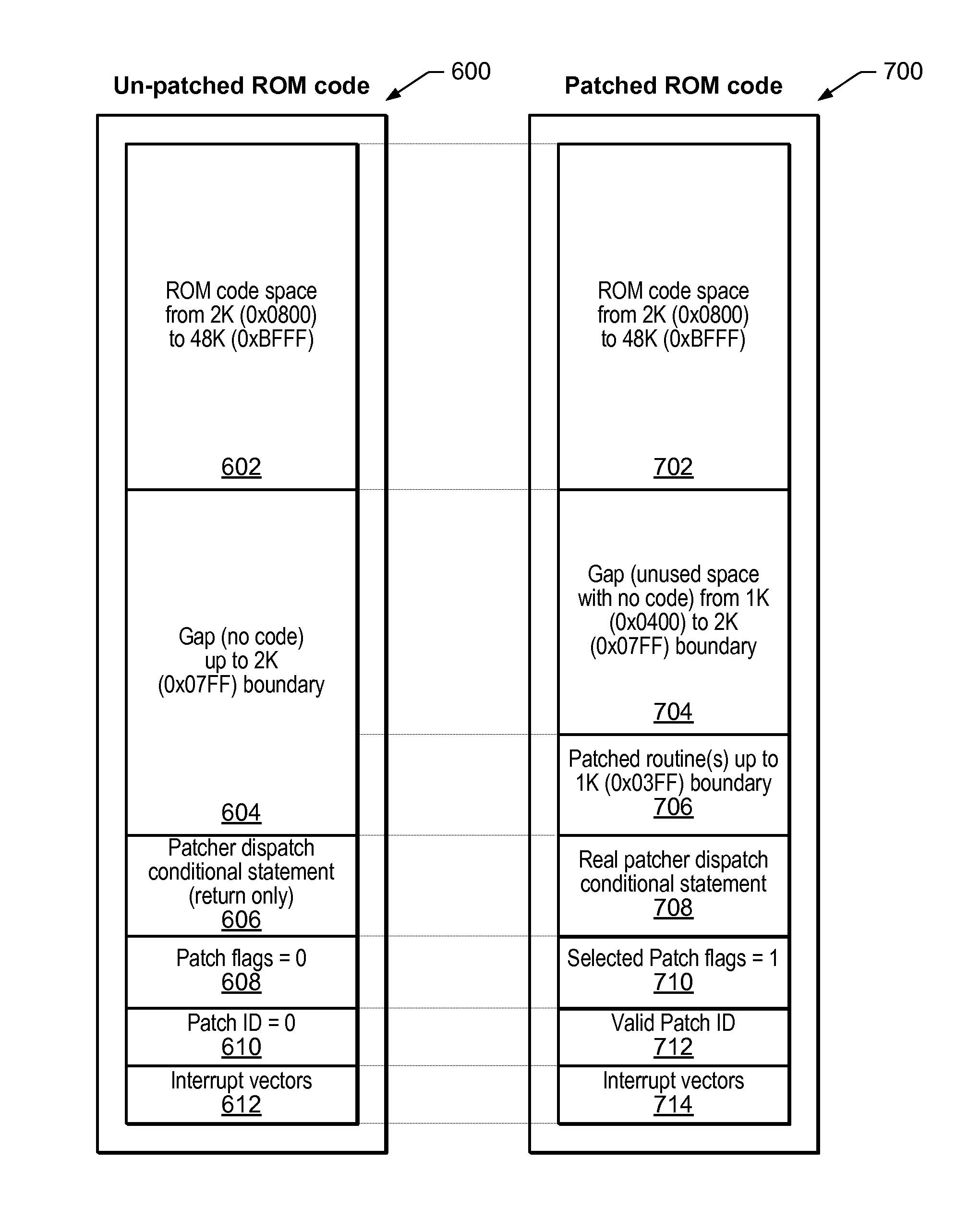
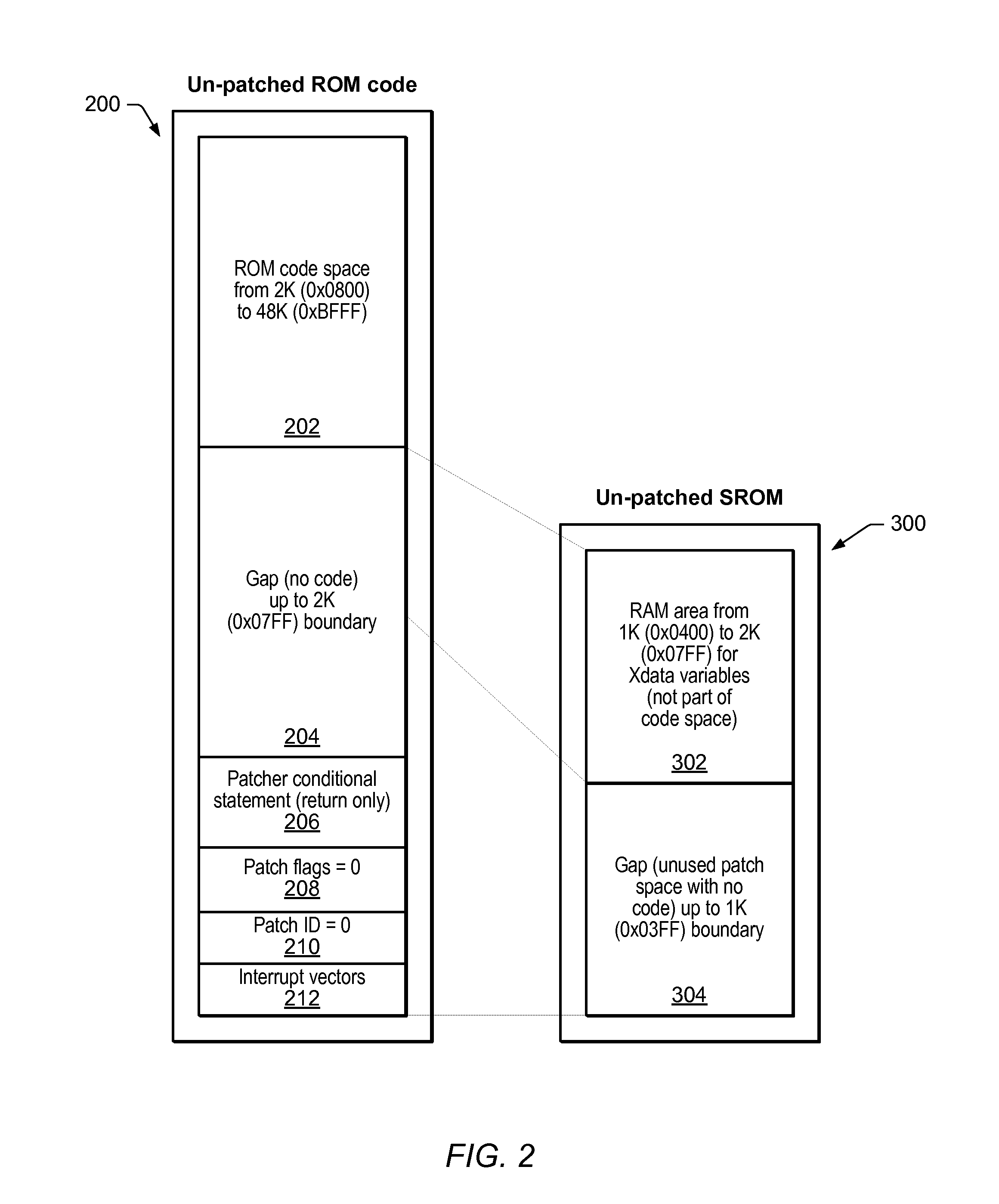
A system in which firmware residing in ROM may be upgraded without re-spinning silicon. A one-bit flag may be assigned for each patchable function representing a firmware upgrade. The first statement of each function may check its associated flag and determine if patch-code should be executed in place of the current function residing in ROM. If the flag is not set, the code may continue executing normally. If the flag is set, a function identifier may be placed into a global memory location, and an assembly language “jump” instruction may be executed, redirecting program control to a specified location in a volatile Scratch Read Only Memory (SROM) where the corresponding patched code may be stored. If more than one function is patched, the global identifier may be used to determine which patched function to execute. Using an assembly language “jump” instruction to redirect control results in the patched function's returning normally to its calling function once it has completed executing.

Description

BACKGROUND OF THE INVENTION[0001]1. Field of the Invention[0002]This invention relates generally to the field of ROM-based system design, and more particularly, to the design of a system in which firmware modules or subroutines residing in ROM may be upgraded without re-spinning silicon.[0003]2. Description of the Related Art[0004]In computing, firmware typically refers to software embedded in a hardware device such as a read-only memory (ROM), most often implemented as an integrated circuit. Firmware can also reside in an erasable programmable read-only memory (EPROM) chip whose program may be modified by special external hardware, oftentimes utilizing optical means such as ultraviolet light, or an electrically erasable programmable read-only memory (EEPROM) chip whose program may be modified by special electrical external hardware different from the ultraviolet light used for configuring EPROMS (as mentioned above).[0005]In general, EEPROMS have become fairly fast, large and compa...

Claims


Application Information

Patent Timeline
Patent Type & Authority Patents(United States)
IPC IPC(8): G06F9/44G06F11/36
CPCG06F11/3644G06F11/3648G06F11/3628
Inventor ODLIVAK, ANDREW J.KUMAR, RAVINDRASTEARNS, WARREN R.ROCKFORD, JOHN GLEN
Owner MICROCHIP TECH INC
Learn More