Microsurgical robot system

a robot system and microsurgical technology, applied in the field of robotic systems, can solve the problems of putting the performing surgeon in a physically strained position for the duration of the procedure, accuracy close to the limit of human capability, and high concentration, so as to reduce the amount of preliminary training, reduce the amount of training, and reduce the effect of labor intensity

Active Publication Date: 2016-05-31
TECH UNIV EINDHOVEN
View PDF9 Cites 3 Cited by
  • Summary
  • Abstract
  • Description
  • Claims
  • Application Information

AI Technical Summary

Benefits of technology

[0007]The kinematic properties of the master and slave units are based on the anatomy of a human hand holding a microsurgical instrument, which makes the dynamic behavior of the system highly intuitive for microsurgeons. The predictability of the motion trajectories of the slave unit makes it possible to use the system in a multi-person setup. Also, it reduces the amount of preliminary training required to operate the device.
[0008]The structural layouts of the master and slave units are identical and highly symmetrical, which is one of the unique design features of the system. By using a virtual wrist joint and an extended parallelogram the units are balanced against gravitational pull. Each master or slave unit has six active degrees of freedom, which are formed by serially placing three differential gears along the extended parallelogram layout. Each differential gear is contained by a differential module built of two identical halves, each able to function independently. This creates a system that is easy controllable, robust, and cost-effective.

Problems solved by technology

Microsurgery demands a high degree of concentration and may put the performing surgeon in a physically strained position for the duration of the procedure.
Some operations require accuracy close to the limit of human capability while others need to be finished within a certain time, putting a great physical as well as mental burden on these surgeons.
Most of these procedures have typical waiting lists of over 100 patients at any time, mainly due to capacity problems.

Method used


Image

  • Microsurgical robot system
  • Microsurgical robot system
  • Microsurgical robot system

Examples


Embodiment Construction

Kinematics

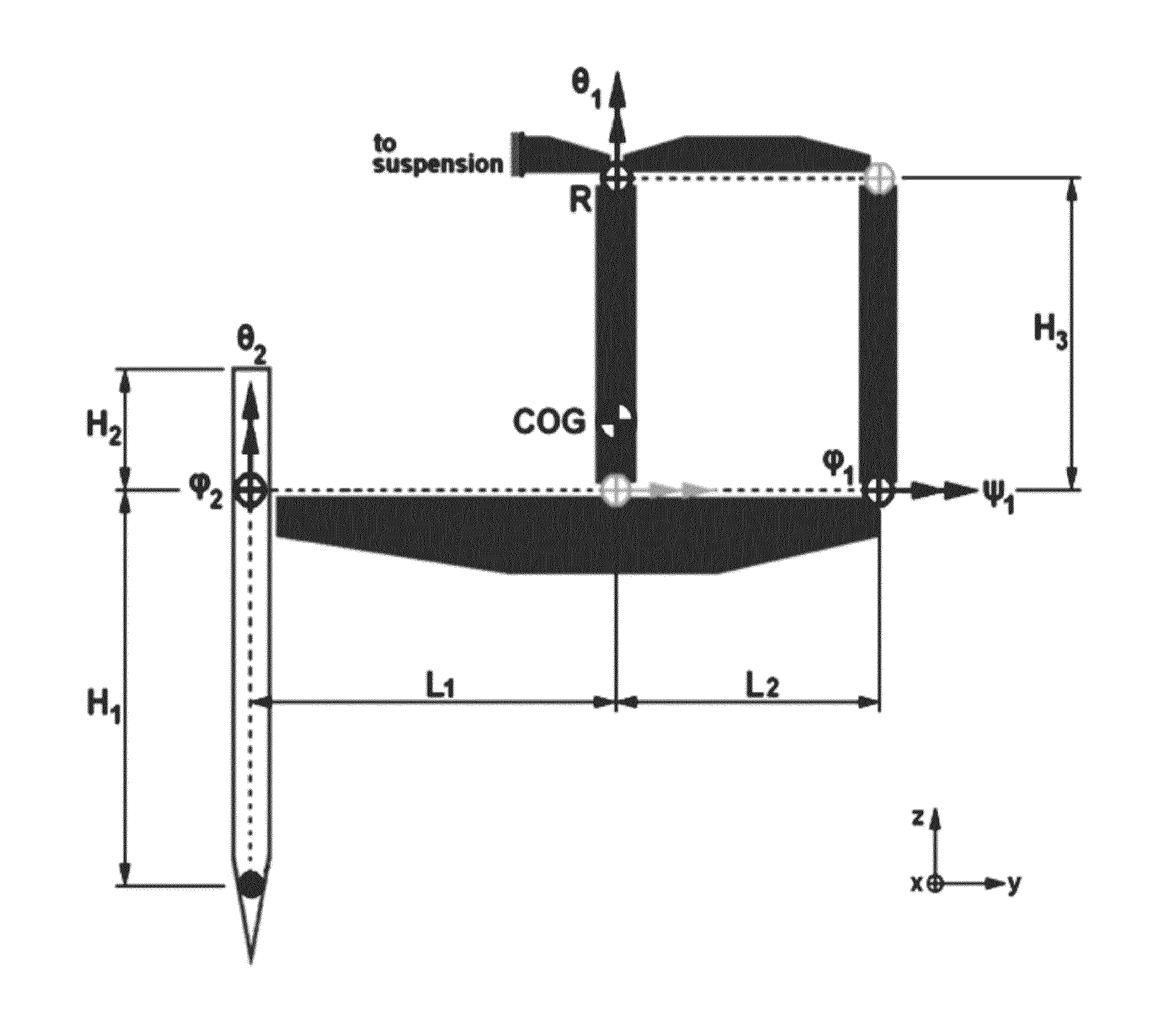
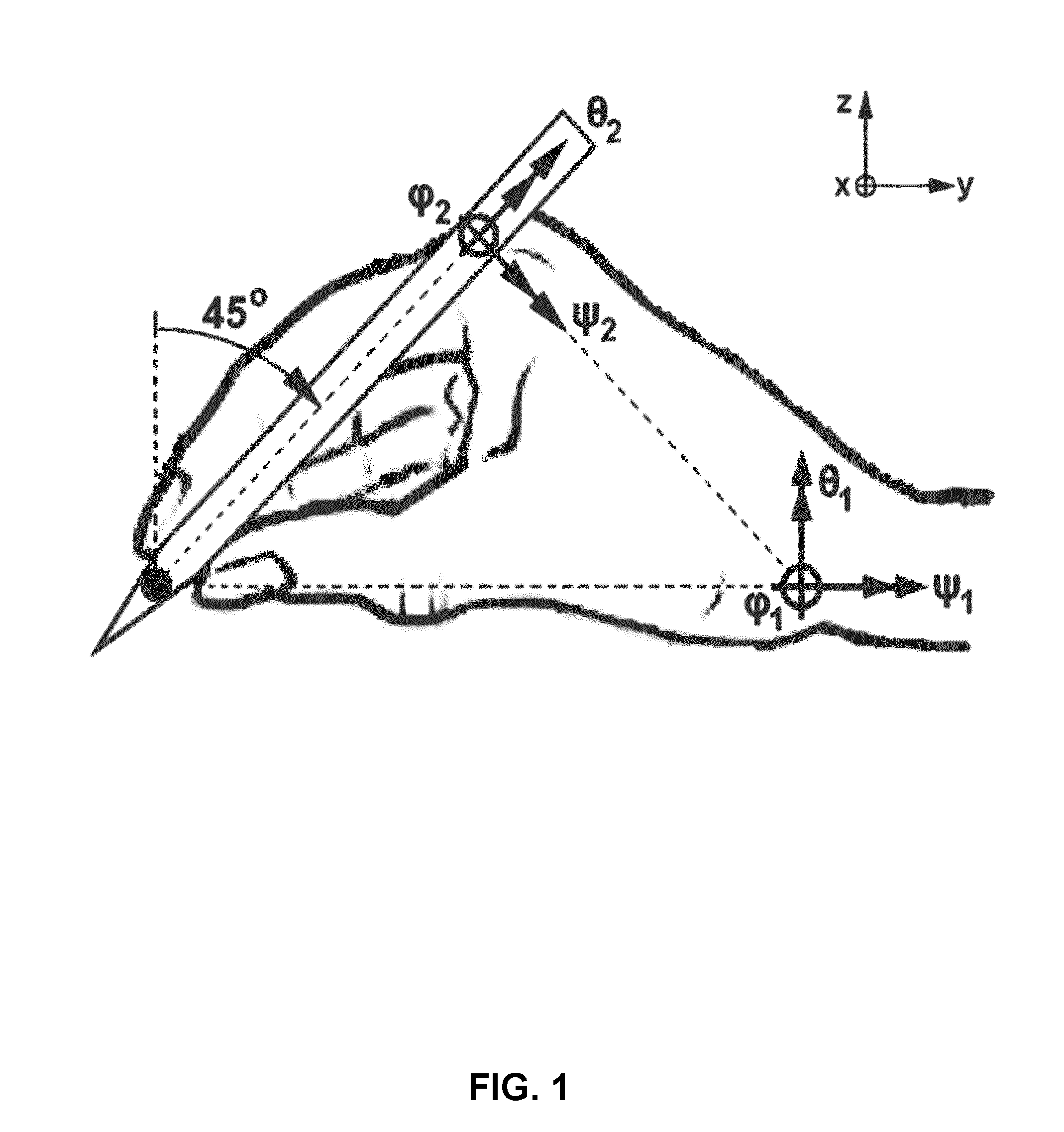
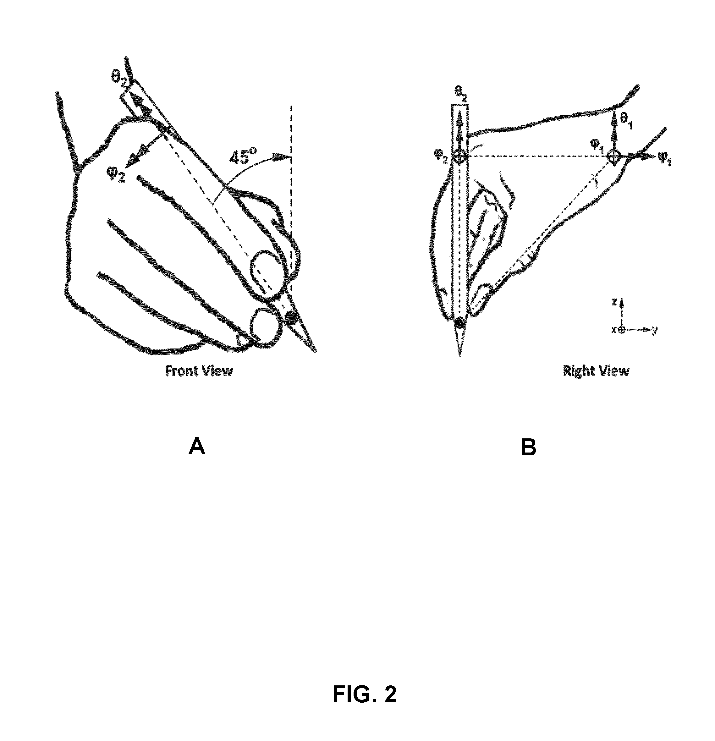
[0037]The range of motion and kinematics of both the master and slave design are based on the anatomy of a human hand holding a pen shaped object, with the wrist joint being a fixed point in space and the tip of the pen being the end effector (FIG. 1). It is a unique feature that makes master and slave have similar kinematics. This implies that the design has 6-DOF, being one spherical joint at the wrist and another at the base of the index finger where the pen is supported. This is the natural and recommended grip for surgeons to hold a microsurgical instrument, whereas the instrument shaft makes a 45 degree angle with the operating plane (FIG. 1).

[0038]The spherical joint at the wrist is used to make large motions with relatively low accuracy, while the spherical joint at the fingers is used to make smaller motions with high accuracy. In practice, when holding a pen the freedom of movement of the rotations of the spherical joint at the fingers is limited to a few degrees...


PUM


Abstract

Designs for modular microsurgical robotic devices and systems are provided, which could include one or multiple master-slave units coupled to a central microscope-based suspension structure. One of the main objectives is to provide robotic assistance during tasks which require long-term user concentration and high precision. The microsurgical robotic devices pay attention to motion scaling and tremor filtration in a 6 Degrees-of-Freedom (DOF) master-slave setup with force feedback. An extra DOF is included to actuate a 1-DOF instrument tip. Embodiments of this invention can be used in the medical environment as well as in other areas such as printed circuit board repair, watch and jewelry making, laboratory tasks, or other areas which require high precision over extended periods of time.

Description

CROSS-REFERENCE TO RELATED APPLICATIONS[0001]This application is a 371 of PCT / EP2012 / 063674 filed on Jul. 12, 2012. PCT / EP2012 / 063674 filed on Jul. 12, 2012 claims the benefit of U.S. 61 / 572,317 filed on Jul. 13, 2011.FIELD OF THE INVENTION[0002]This invention relates to robotic systems. In particular, the invention relates to microsurgical devices and systems.BACKGROUND OF THE INVENTION[0003]Microsurgery demands a high degree of concentration and may put the performing surgeon in a physically strained position for the duration of the procedure. Some operations require accuracy close to the limit of human capability while others need to be finished within a certain time, putting a great physical as well as mental burden on these surgeons. Hence, the population of microsurgeons is relatively small compared to that of general surgeons. Meanwhile, microsurgery is one of the most trending fields of modern surgery, amongst which several reconstructive procedures and tissue transplantatio...

Claims


Application Information

Patent Timeline
Patent Type & Authority Patents(United States)
IPC IPC(8): A61B34/30
CPCA61B34/30A61B34/75Y10S901/25Y10S901/41A61B34/37
Inventor CAU, RAIMONDO
Owner TECH UNIV EINDHOVEN
Why Eureka
Try Eureka