Remote controlled firearm safety locking system

a remote controlled and locking system technology, applied in the direction of safety arrangement, weapon components, weapons, etc., can solve the problems of encumbering the firearm, affecting the safety of the firearm, and the most practical and expensive of these systems

Active Publication Date: 2016-05-31
FIDLOW HAL
View PDF2 Cites 3 Cited by
  • Summary
  • Abstract
  • Description
  • Claims
  • Application Information

AI Technical Summary

Benefits of technology

[0003]It is thus an object of the present invention to provide a remote controlled firearm safety l

Problems solved by technology

For instance, oftentimes there are serious questions as to whether the discharge of a weapon is necessary or Whether it is best that the weapon be disarmed to prevent it from being fired.
Such circumstances may dictate that a weapon be disabled.
However, most of these systems are not practical or are very expensive to manufacture and ins

Method used


Image

  • Remote controlled firearm safety locking system
  • Remote controlled firearm safety locking system
  • Remote controlled firearm safety locking system

Examples


Embodiment Construction

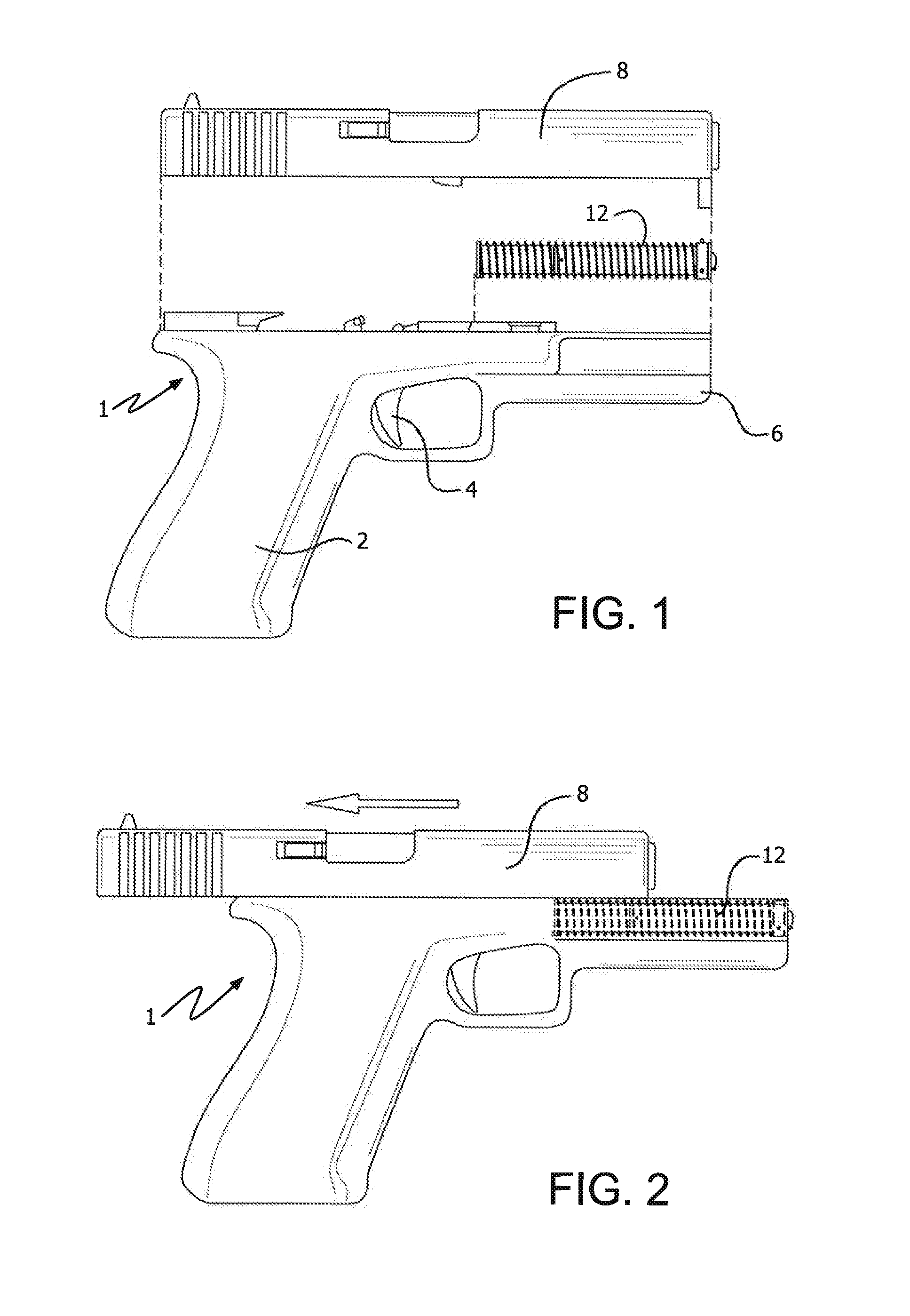
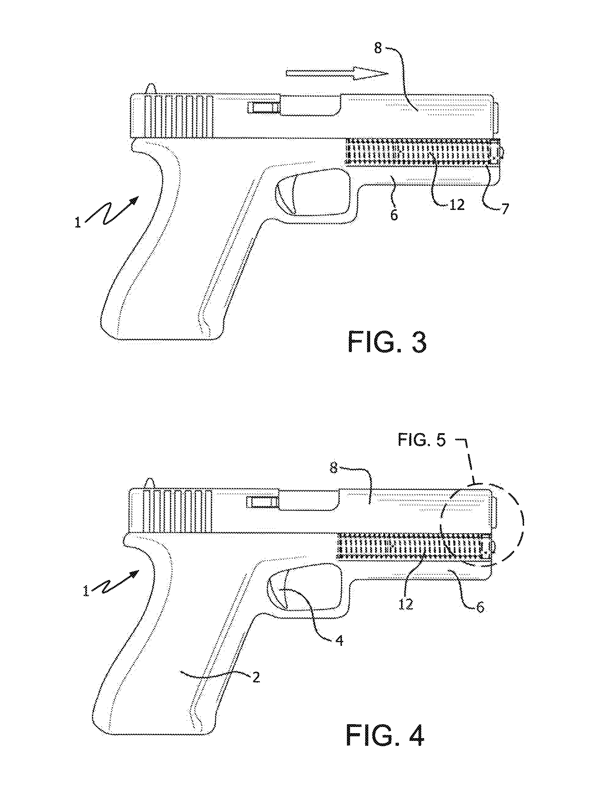
[0020]Handgun 1, a Glock Gen 4 or similar “Glock” type handgun, comprises gun body 2 having trigger 4 and gun barrel or muzzle section 6 and slide member 8. Recoil spring guide assembly cavity 7 is located within muzzle section 6. As is standard in “Glock” type handguns, slide member 8 is configured to be slideably moveable over and along muzzle section 6 and gun body 2. In order to fire handgun 1, slide member 8 must be slid back and then pushed fully forward, over muzzle section 6. This ensures that handgun 1 is cocked, ready to load and upon pulling trigger 4, to be fired.

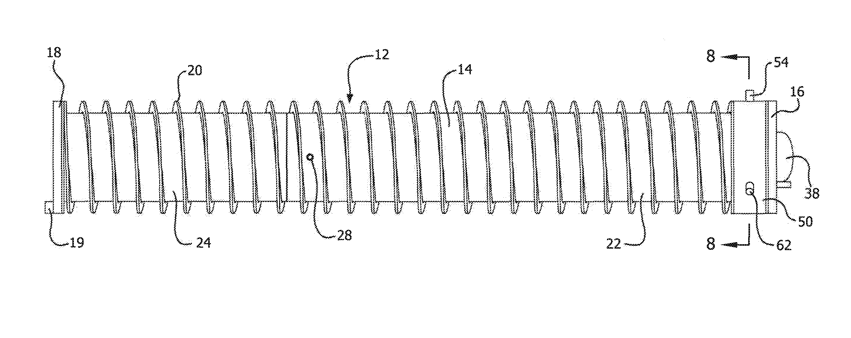
[0021]Recoil spring guide assembly 12 is configured to replace the standard recoil spring guide in muzzle section 6 of handgun 1. Assembly 12 comprises outer casing or housing 14. Casing 14 is optimally made of corrosion resistant steel or similar metal. Recoil spring 20 circumscribes housing 14. Recoil spring retention walls 16 and 18 of assembly 12 are located at the ends of casing 14. Raised notch 19 is provi...


PUM


Abstract

A remote controlled firearm safety system is provided for a “Glock” type handgun having a slide member, moveable over and along a muzzle section. The recoil spring guide assembly of the weapon, installed in the muzzle section, has a flange member with a plurality of socket openings. Each socket opening contains a locking pin which is moveable between a stored position within the socket openings and an extended position. When the locking pins are extended out of the socket openings, they extend partially into the muzzle section. This prevents the slide member from being cocked and the weapon from being fired. The movement of the locking pins is controlled by a signal receiving device within the recoil spring guide assembly. Upon receipt of a remote signal by the receiving device, a motor drive and a mechanical linkage are actuated to move the locking pins out of the socket openings.

Description

BACKGROUND OF THE INVENTION[0001]The use of firearms by local, state, and federal law enforcement personnel, as well as the military and private security sectors, presents a variety of situations in which the circumstances surrounding this usage becomes an issue. For instance, oftentimes there are serious questions as to whether the discharge of a weapon is necessary or Whether it is best that the weapon be disarmed to prevent it from being fired. Such circumstances may dictate that a weapon be disabled. By way of examples only, if the firearm should fall into the hands of unauthorized or dangerous individuals, if the weapon is lost or unaccounted for, or if it is not appropriate that the weapon be fired in a given situation, disabling that weapon, especially from a remote location, may not only be beneficial, but it also may be necessary in the interest of safety and even to save lives.[0002]There are numerous s which have been proposed for locking or disabling a firearm from a rem...

Claims


Application Information

Patent Timeline
IPC IPC(8): F41A17/00F41A17/06
CPCF41A17/06F41A17/063F41A17/42
Inventor FIDLOW, HAL
Owner FIDLOW HAL
Why Eureka
Try Eureka