

Integrated circuit with a control input that can be disabled
a technology of integrated circuits and control inputs, applied in the field of integrated circuits, can solve the problems of not enabling the defective dut for further tests, e.g., write operations,
- Summary
- Abstract
- Description
- Claims
- Application Information
AI Technical Summary
Benefits of technology
Problems solved by technology
Method used
Image

Examples
first embodiment
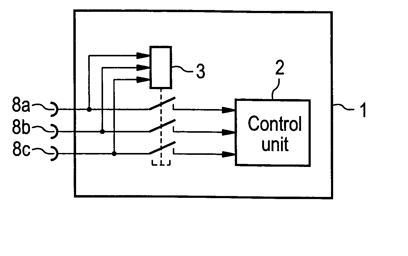
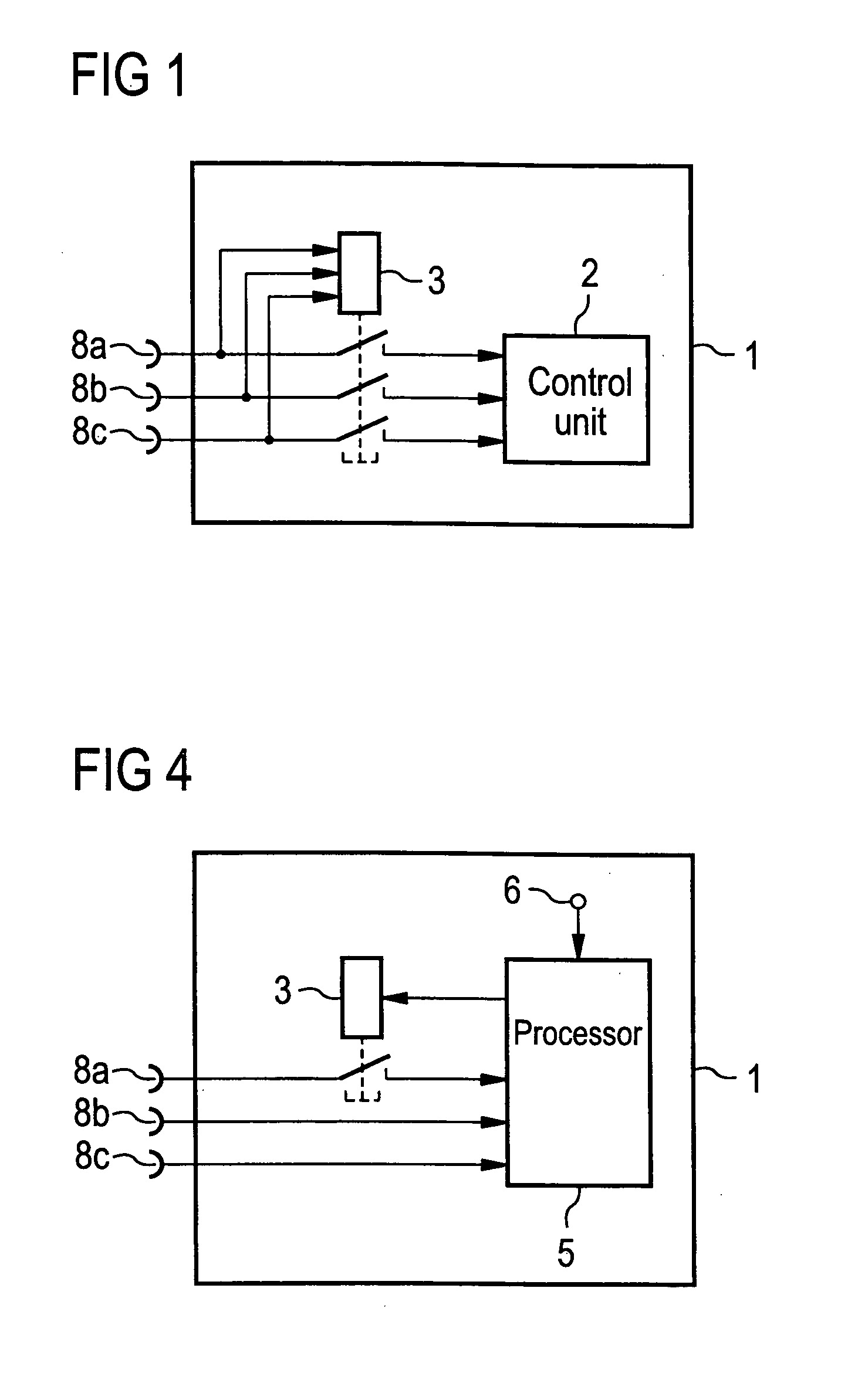
[0037]FIG. 1 shows the present invention. An integrated circuit 1 includes a control unit 2 and a deactivation circuit 3. It further includes a plurality of control inputs 8a, 8b and 8c for the provision of input signals to the control unit 2. In the illustrated embodiment of the present invention, the provision of control signals from all three control lines 8a, 8b and 8c can be disabled together by the deactivation circuit 3. The deactivation circuit 3 is also coupled to the control inputs 8a, 8b and 8c. The deactivation circuit 3 is activated once a particular combination of control signals is received from the three control inputs 8a, 8b and 8c, for example a high voltage level, e.g., 3.3V, on all three control inputs 8a, 8b and 8c. Once the deactivation circuit 3 has been activated the control unit 2 does not receive any further input signals from the control inputs 8.
[0038] Because the deactivation circuit 3 is connected to the plurality of control inputs 8 directly, the deact...
second embodiment
[0051]FIG. 4 shows the present invention. An integrated circuit 1 comprises a processor 5 and a deactivation circuit 3. In the presented embodiment, three control inputs 8a, 8b and 8c are connected to the processor 5. The processor 5 is further connected to an input 6 for receiving program instructions. The processor 5 is also connected to the deactivation circuit 3. In the embodiment presented in FIG. 4 only the provision of control signals from one control input 8a can be disabled using the deactivation circuit 3.
[0052] The deactivation circuit 3 is controlled by the processor 5. Upon receiving a predefined program instruction from the input 6, the processor 5 will activate the deactivation circuit 3 and in this way disable the control input 8a. The program instruction triggering the disablement of control input 8a can be loaded from an internal storing program instruction or may be provided externally to the integrated circuit 1.
[0053] In the embodiment shown in FIG. 4, a second...
third embodiment
[0056]FIG. 5 shows the present invention. An integrated circuit 1 comprises a control unit 2 and a deactivation circuit 3. The integrated circuit 1 further comprises three control inputs 8a, 8b and 8c, which are connected to the control unit 2. Only the provision of control signals from one of these control inputs 8, the control input 8a can be disabled by using the deactivation circuit 3. The deactivating circuit 3 is controlled by a control register 7, which is connected to the control unit 2.
[0057] The deactivation circuit 3 is activated once a first predefined value is written into the control register 7. The writing of the predefined first value into the control register 7 can be triggered for example by the control unit 2 or using a combination of input signals provided to the control inputs 8 or by directly writing a new value into the control register 7 using an address bus and a data bus to the integrated circuit 1, which are not shown in FIG. 5.
[0058] In the embodiment sh...
PUM
 Abstract
Description
Claims
Application Information