Retrofit LED lamp

a technology of led lamps and led lamps, applied in the direction of elongated light sources, semiconductor devices of light sources, lighting and heating apparatus, etc., can solve the problems of quite different output power of lamps for different types of ballasts, and achieve the effects of low impedance, high impedance, and effective disassembly and installation

Active Publication Date: 2019-10-31
SIGNIFY HLDG BV
View PDF2 Cites 3 Cited by
  • Summary
  • Abstract
  • Description
  • Claims
  • Application Information

AI Technical Summary

Benefits of technology

[0040]More specifically, an instant start electronic ballast, for example for a T8 size fluorescent tube lamp, for example delivers approximately half the output current of an electromagnetic ballast for the T12 size fluorescent tube lamp and the program start / rapid start electronic ballast for T12 size fluorescent tube lamp. By using a parallel configuration for the higher current electromagnetic ballast, or program start electronic ballast or rapid start electronic ballast, the current is split between two branches, each with a lower string voltage. Thus, the total power is reduced and matches the power when the same lamp is driven by an instant start electronic ballast wherein the LED segments are series re-configured for the instant start electronic ballast. Those ballasts with different output currents can be differentiated by whether the ballast outputs a heating voltage to the filament of the lamp. Thus the embodiment of the invention proposes to re-configure the LED segment according to the existing of the heating voltage or not. In this way, the LED configuration is set to match the current delivery to the lamp, without using complex detection technology such as frequency detection to differentiate the ballasts. In particular, this design gives better energy saving performance for a lamp which can be driven by both electronic and electromagnetic ballasts. Here the term “rated” in the claims means the ballast operating as a current source to output this current, substantially regardless of the impedance of the load.
[0044]This embodiment provides a retrofit lamp for fluorescent lamps. Traditional fluorescent lamps are used with different types of ballasts with or without a lamp filament interfacing circuit, and this embodiment provides compatibility for both types.
[0060]The first and second detection units for example each comprise a gated switch comprising power terminals and a control terminal, wherein said gated switch is adapted to connect the second diode bridge rectifier if a voltage between the pair of pins exceeds a threshold. This embodiment achieves both function of detection and reconfiguration by the same gated switch component, and saves component number and cost.
[0062]The TRIAC for example responds to a gate current. A voltage across the pins can be thus be converted to a current. The filter circuit avoid erroneous triggering of the TRIAC by providing a path for noise current (smoothing the noise current) which then does not enter the gate of the TRIAC.
[0064]Each gated switch is for example between one connection pin of a respective pair of connection pins and an input to the second diode bridge rectifier via the power terminals, and the control terminal is connected to the other connection pin of a corresponding pair of connection pins. It thus allows or prevents current flow to (or from) the second diode bridge rectifier, and thus either enables or disables the parallel configuration. Disabling the parallel configuration provides pin safety function. When in the parallel configuration is enabled, the diodes in the circuit automatically implement the parallel configuration instead of the series configuration. Thus, the parallel configuration has lower impedance and in turn effectively disables the series configuration which not only has high impedance of series LED but also has the extra capacitance.

Problems solved by technology

A technical problem of this is that the lamp has quite different output power for different types of ballasts.

Method used


Image

  • Retrofit LED lamp
  • Retrofit LED lamp
  • Retrofit LED lamp

Examples


Embodiment Construction

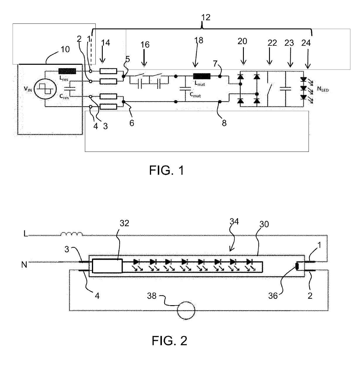
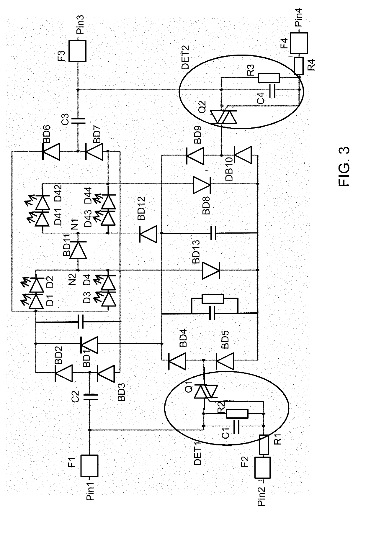
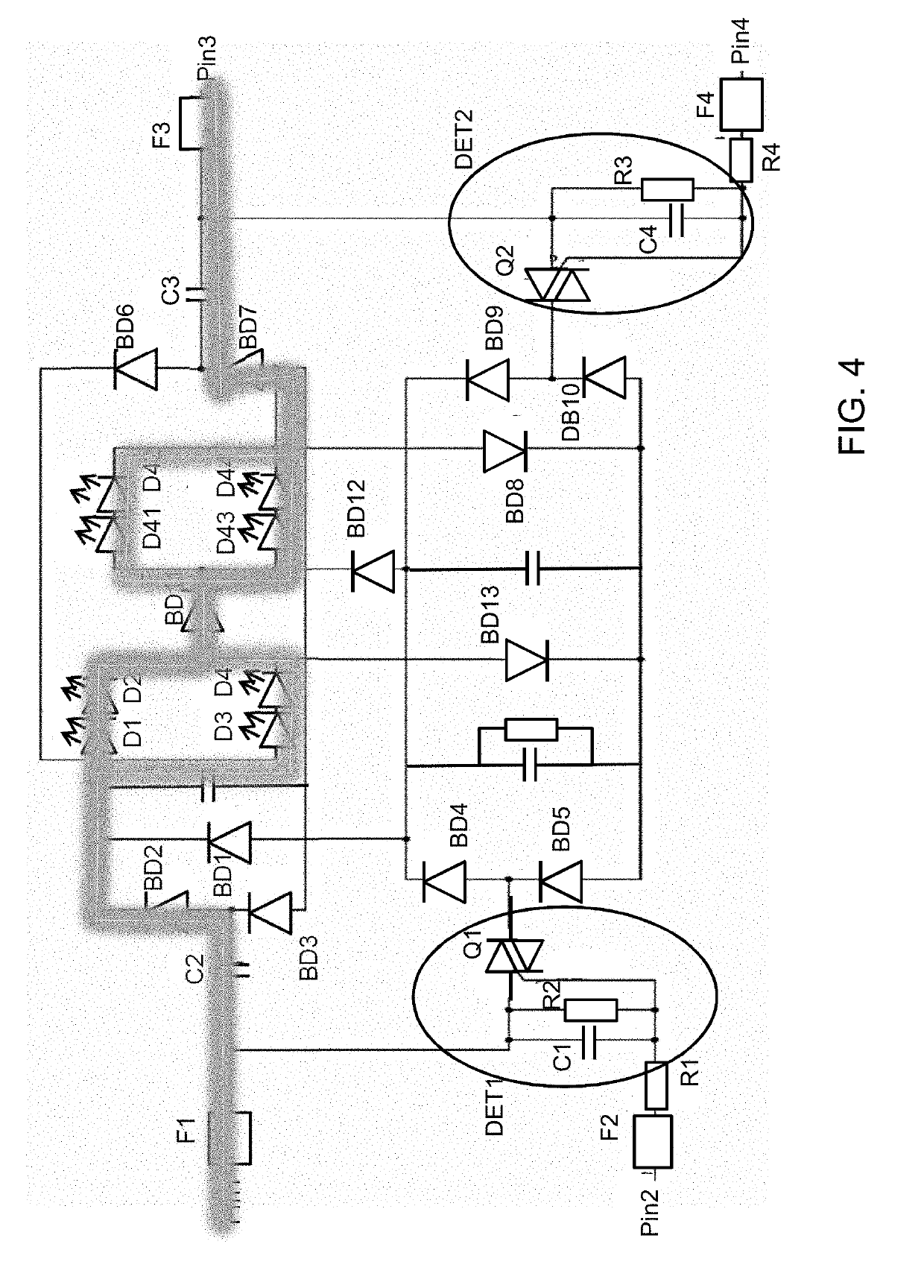
[0077]The invention will be described with reference to the Figures. It should be understood that the detailed description and specific examples, while indicating exemplary embodiments of the apparatus, systems and methods, are intended for purposes of illustration only and are not intended to limit the scope of the invention. These and other features, aspects, and advantages of the apparatus, systems and methods of the present invention will become better understood from the following description, appended claims, and accompanying drawings. It should be understood that the Figures are merely schematic and are not drawn to scale. It should also be understood that the same reference numerals are used throughout the Figures to indicate the same or similar parts.

[0078]The invention provides a retrofit lamp to be used with a fluorescence lighting ballast. A detection circuit detects (at least) if a connected ballast is a ballast with low output current or a ballast with high output curr...


PUM


Abstract

A retrofit lamp is for use with a fluorescence lighting ballast. The retrofit lamp comprises a filament emulation circuit. A detection circuit detects (at least) if a connected ballast is an instant start electronic ballast or an electromagnetic ballast by detecting a potentially existing heating voltage across the filament emulation circuit. In response, an LED arrangement may be connected in a series configuration (for an instant start electronic ballast) or in a parallel configuration (for an electromagnetic ballast). In this way, the output power is managed to ensure efficient operation. A different pin safety function may also be provided in the different configurations.

Description

FIELD OF THE INVENTION[0001]The invention relates to retrofit LED lamps, such as tubular LEDs (TLEDs), suitable for connection to a fluorescent ballast.BACKGROUND OF THE INVENTION[0002]Solid state lighting (SSL) is rapidly becoming the norm in many lighting applications. This is because SSL elements such as light emitting diodes (LEDs) can exhibit superior lifetime and energy consumption, as well as enabling controllable light output color, intensity, beam spread and / or lighting direction.[0003]Tubular lighting devices are widely used in commercial lighting applications, such as for office lighting, for retail environments, in corridors, in hotels, etc. A conventional tubular light fitting has a socket connector at each end for making mechanical and electrical connection to connection pins at each end of a tubular light. Conventional tubular lights are in the form of fluorescent light tubes. There is a huge installed base of luminaires equipped with electromagnetic or electronic bal...

Claims


Application Information

Patent Timeline
Patent Type & Authority Applications(United States)
IPC IPC(8): H05B33/08F21V23/02F21K9/27H05B44/00
CPCF21K9/27F21Y2115/10F21Y2103/10F21V23/02H05B33/083H05B33/0809H05B33/0884H05B33/0827H05B45/44Y02B20/30H05B45/357H05B47/20H05B45/46H05B45/48
Inventor WU, XIUJUANLU, HANZHOU, JING XUYANG, JASON J.WANG, JESSIEELLA, TIAN
Owner SIGNIFY HLDG BV
Why Eureka
Try Eureka