Arrangement for use in a projection exposure tool for microlithography having a reflective optical element

a technology of exposure tool and microlithography, which is applied in the direction of optical radiation measurement, printers, instruments, etc., can solve the problems of changing the reflectivity of individual or all mirrors, and the reflective optical element now has regions which are no longer reflective, so as to achieve the effect of minimizing the photosensitive layer

Active Publication Date: 2016-05-31
CARL ZEISS SMT GMBH +1
View PDF17 Cites 0 Cited by
  • Summary
  • Abstract
  • Description
  • Claims
  • Application Information

AI Technical Summary

Benefits of technology

[0007]It is an object of the invention to provide an arrangement with a reflective optical element and a method for measuring the intensity or a temperature on a reflective optical element of a projection exposure tool for microlithography with which the aforementioned problems are resolved, and in particular a change over time in the irradiation conditions on the structure-carrying mask and the photosensitive layer can be minimized. Further, it is an object to make monitoring of the incoming radiation possible without recesses in the reflective coating of the optical element being necessary.
[0035]The above arrangement allows the temperature distribution in the reflective optical element to be monitored. Especially a change over time in the temperature distribution can be detected. This information can be used to take measures correcting the temperature distribution, e.g. be localized heating. This way deviations in the imaging characteristics of the reflective optical element can be minimized.
[0036]According to an embodiment, material emitting the secondary radiation comprises a low expansion material as specified in this application, in particular silicate glass. According to a variation, the low expansion material is doped in order to enhance the temperature dependence of the radiation conversion efficiency.
[0043]For illumination optics it is advantageous if the reflective optical element is disposed close to a pupil plane of the illumination optics and the arrangement comprises an evaluation device which is configured to determine a spatially resolved intensity distribution of the exposure radiation irradiated onto the reflective optical element, and by means of the correction unit an intensity distribution in the same or a different pupil plane can be changed. According to a further embodiment the optical element is disposed close to a field plane of the illumination optics, and by means of the correction unit an intensity distribution in this or a different field plane can be changed.

Problems solved by technology

However, during operation various influences can change the irradiation conditions on the structure-carrying mask and the photosensitive layer.
Furthermore, e.g. contaminations can also lead to the reflectivity of individual or of all of the mirrors changing.
The disadvantage of this, however, is that the reflective optical element now has regions which are no longer reflective.

Method used


Image

  • Arrangement for use in a projection exposure tool for microlithography having a reflective optical element
  • Arrangement for use in a projection exposure tool for microlithography having a reflective optical element
  • Arrangement for use in a projection exposure tool for microlithography having a reflective optical element

Examples


Embodiment Construction

[0065]In the exemplary embodiments described below elements which are similar to one another functionally or structurally are provided as far as possible with the same or similar reference numbers. Therefore, in order to understand the features of the individual elements of a specific exemplary embodiment, reference should be made to the description of other exemplary embodiments or to the general description of the invention.

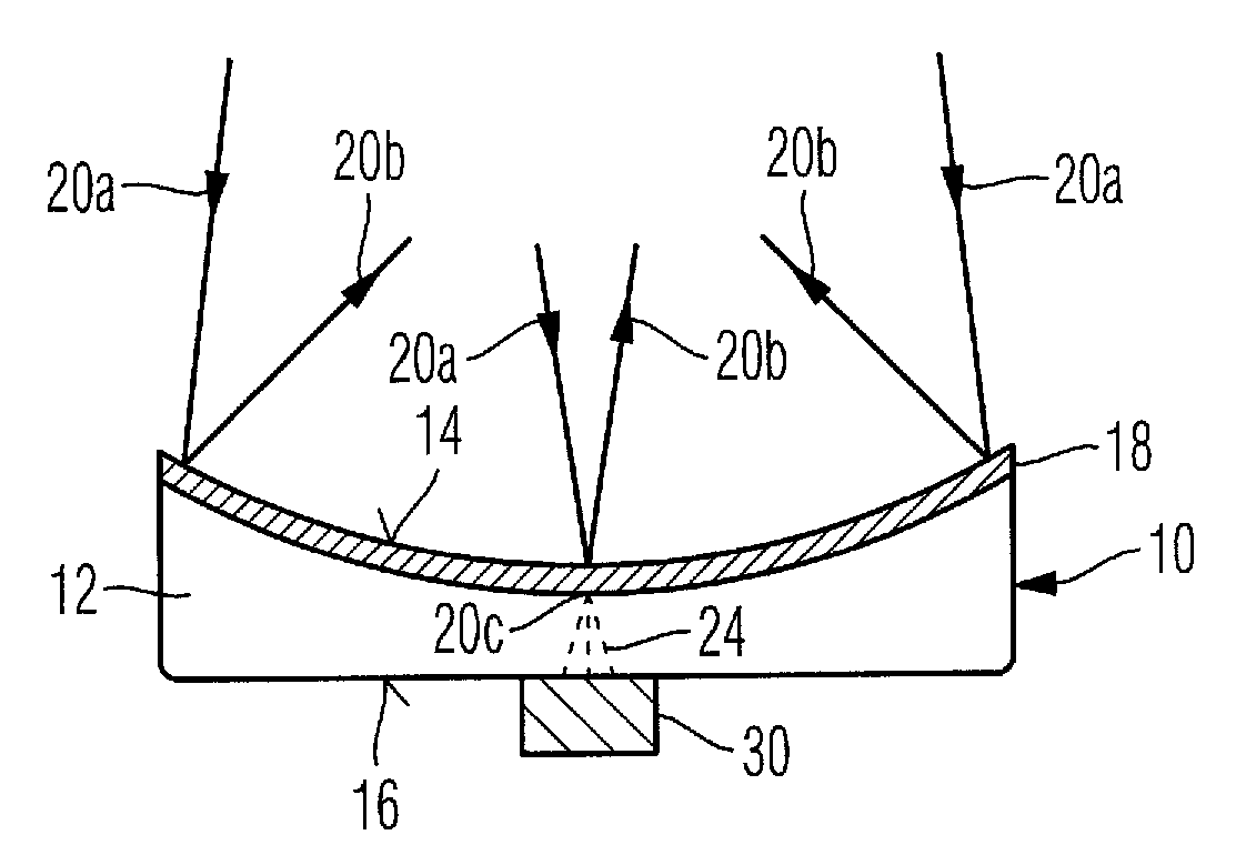
[0066]FIG. 1 shows an exemplary embodiment of an arrangement according to the invention of a reflective optical element 10 and a radiation detector 30. The reflective optical element 10 is designed in the form of a concave mirror for use in a projection exposure tool for microlithography. For this purpose the reflective optical element 10 comprises a carrier element 12 having the form of the mirror surface. The carrier element 12 guarantees the mechanical strength of the optical element 10, and at the same time guarantees the function of the latter. The carrier...


PUM

PropertyMeasurementUnit
wavelengthaaaaaaaaaa
temperatureaaaaaaaaaa
wavelength rangeaaaaaaaaaa

Abstract

An arrangement for use in a projection exposure tool (100) for microlithography comprises a reflective optical element (10; 110) and a radiation detector (30; 32; 130). The reflective optical element (10; 110) comprises a carrier element (12) guaranteeing the mechanical strength of the optical element (10; 110) and a reflective coating (18) disposed on the carrier element (12) for reflecting a use radiation (20a). The carrier element (12) is made of a material which upon interaction with the use radiation (20a) emits a secondary radiation (24) the wavelength of which differs from the wavelength of the use radiation (20a), and the radiation detector (30; 32; 130) is configured to detect the secondary radiation (24).

Description

CROSS REFERENCE TO RELATED APPLICATIONS[0001]This application is a continuation application of international patent application PCT / EP 2011 / 000385, filed Jan. 28, 2011, designating the United States and claims priority of German patent application no. 10 2010 006 326.6, filed Jan. 29, 2010, and the U.S. provisional application No. 61 / 282,367 filed Jan. 29, 2010, and the entire contents of all of the above applications are incorporated herein by reference.FIELD OF THE INVENTION[0002]The present invention relates to an arrangement for use in a projection exposure tool for microlithography comprising a reflective optical element, an optics module, to a projection exposure tool with this type of arrangement, to a method of measuring the intensity on a reflective optical element of a projection exposure tool, and to a method of measuring a temperature on an optical element of a projection exposure tool for microlithography.BACKGROUND OF THE INVENTION[0003]Projection exposure tools for mi...

Claims


Application Information

Patent Timeline
Patent Type & Authority Patents(United States)
IPC IPC(8): G03B27/52G02B5/08G01J1/58G03F7/20G03B27/54
CPCG03F7/70891G01J1/58G02B5/0891G03F7/7085G03F7/70316G03F7/70558G03F7/70958
Inventor EHM, DIRK HEINRICHVAN KAMPEN, MAARTENSCHMIDT, STEFAN-WOLFGANGBANINE, VADIM YEVGENYEVICHLOOPSTRA, ERIK
Owner CARL ZEISS SMT GMBH
Why Eureka
Try Eureka